How to import a Yokogawa Stardom configuration
The Smart Generator for Stardom generates the following in the PcVue project based on a Yokogawa Stardom configuration:
-
OPC data acquisition between PcVue and the Stardom FCN-FCJ OPC Server.
-
I/O variables including mapping onto the OPC-DA client driver.
-
Mimics by associating HMI symbols with the Stardom project's Program Organization Units (POUs). The mimics that can be generated are: Trend mimics, control group mimics, graphics mimics (free mimics), and the system overview mimic. The latter mimic includes: One controller symbol for each controller and an information panel (Faceplate) for each controller type (FCN and FCJ).
The smart generator uses the Stardom Library to provide the specialized components for the HMI:
-
The Toolbox mimic.
-
Mimic templates.
-
Function key settings.
-
NPAS/POU symbols.
-
Global variable symbols.
-
Other symbols.
See the Stardom Library folder section of this topic for more information.
Prerequisites
-
You have exported the Stardom project. This is a file exported from the Yokogawa Stardom Logic Designer in IEC61131-3 (ASCII) format.
-
You have installed and stored the Stardom library folder in the PcVue project sub-folder LIB.
To operate PcVue in communication with the Stardom network, the Stardom FCN-FCJ OPC Server must be running.
The Stardom Logic Designer does not need to be running during the import process.
Consultez la rubrique Généralités sur les Smart Generators pour en savoir plus.
Sélectionner les données source
Avant de commencer le processus d'import, nous vous recommandons de sauvegarder la configuration des variables PcVue en cas de problème survenant pendant le processus d'import. La configuration des variables est stockée dans le fichier VAREXP.DAT dans le répertoire C du projet.
Assurez-vous que le logiciel PcVue est arrêté avant de copier le fichier.
-
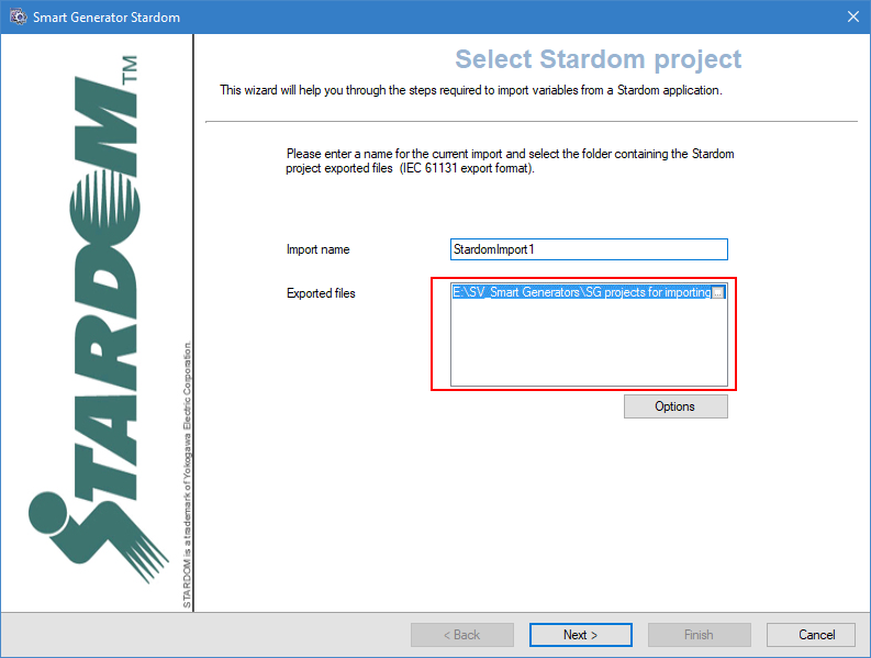
Go to Configure then Smart Generators and click New Stardom import. The Smart Generator Stardom dialog opens with the Import name field specified. You can change this name.
 Show picture
 -
Click on ellipses button in Exported files field and select the location of the Stardom project files to import. The exported files should be in the IEC 61131 format.
-
Cliquez sur le bouton Avancé/Options, puis sélectionnez une liste de serveurs et une liste de clients dans l'onglet Liste multi-postes pour définir le comportement des variables PcVue pour un projet multi-postes.
Les listes de serveurs et de clients doivent avoir été créées préalablement dans PcVue et le poste à partir duquel vous exécutez le smart generator doit être dans la liste des serveurs.
-
Select the OPC server tab and select from the drop downs the default OPC server and group. This configuration applies to global variables only.
The resources declared in the OPC server configuration file (FCXCNF.CSV) must be the same as those declared in the Stardom project.
-
Select the Options tab and select from the drop-down the encoding for the exported files then click OK to validate.
Selecting POUs and import type
After you have selected the source data and configured the networking lists and options of the import via the Select project dialog, the next step is to select the POUs (Program Organization Unit) you want to import and the import type.
-
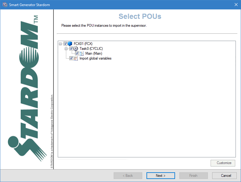
Click Next, the Select POUs dialog opens. Here the POUs are displayed in a tree structure of three levels. The first level is the Controller, the second one is the Task and the third is the Program. Select the items to be imported.
Show picture -
To customize POUs, select them and click Customize. This opens the POUs dialog which enables you to configure several properties for all instances of POUs selected. The list view pane on the left displays the instance name of the selected items. For example: FCX01/Task0/PRG1/PAS_PID_1. The right side of the list view displays the variables. For example: PAS_PID.
In the list view, you can sort the list by clicking on the column headers.
You can also use the Windows keyboard shortcuts for making multiple selections. (Shift+Click and Ctrl+Click).
The grid pane of the right of the dialog displays the properties configured in the STARDOMIMPORTCONFIGURATION.XML file. Click Apply to apply the property changes to the selected POU instances.
-
Click Next, the Import type dialog opens. Select the import type you need. There are three options:
-
Import data - If selected, it only imports the configuration necessary to generate PcVue variables.
-
Import HMI- If selected, it only imports the configuration necessary to generate and structure PcVue mimics (HMI).
-
Full import - If selected, it imports the configuration and generate both the variables and mimics (HMI).
-
Selecting and customizing the variables
After you have selected the POUs to import and the import type via the Select import type dialog, the next step is to select the import type for the global variables, then to select and customize the variables you want to generate.
-
Cliquez sur Suivant, le processus d'import de variables est initialisé et la boîte de dialogue Sélectionner le type d'import s'ouvre. Sélectionnez le type d'import dont vous avez besoin :
- Import personnalisé si vous voulez accéder à la boîte de dialogue Sélectionner les variables dans laquelle vous pouvez filtrer et sélectionner manuellement la liste des variables à importer.
- Import complet si vous voulez générer des variables pour toutes les données source.
-
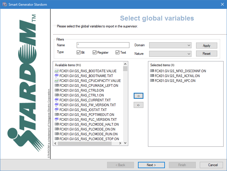
(Option Import personnalisé) Ajustez les filtres pour trouver les variables à importer. Le champ Nom permet de filtrer la liste des variables en fonction du nom dans les données source. Vous pouvez utiliser des caractères joker, l'astérisque (correspond à n'importe quel nombre de caractères) et le point d'interrogation (correspond à un seul caractère).
Par exemple :
'Pump1' ne correspondrait qu'à une donnée source nommée 'Pump1'.
'Pump?' correspondrait à 'Pump1' ou 'Pump2' etc mais pas à 'Pump10'.
'Pump*' correspondrait à 'Pump1', 'Pump2' et 'Pump10' mais également à 'Pumpkin'.Les variables qui correspondent au filtre apparaissent dans le volet Éléments sélectionnés.
-
(Option Import personnalisé) Sélectionnez les variables filtrées dans le volet Eléments disponibles à importer et cliquez sur le bouton avec la flèche droite ->. Les variables du volet Eléments sélectionnés vont être importées et générées.
-
Click Next, the Customize global variables dialog opens. This dialog allows you to modify the properties of multiple variables at a time. Select the variables to modify in the left pane and adjust the properties that are not grayed out in the right pane. Each property that you modify will be applied to all selected variables.
Configuring the HMI
After selecting and customizing the variables to import via the Customize global variables dialog, the next step is to configure the HMI items to be imported.
After making any changes to the properties of an element, you must use click Apply button in the toolbar before selecting another element or clicking Finish. Failing to do so results in the loss of any changes made.
Click Next, the Smart Generator HMI Configuration dialog opens. Here you can configure the structure and some of the contents of the mimics that form the HMI. In addition to the menu and toolbar, the dialog contains two main areas:
-
The Categories configuration tree in the left pane. Right clicking on a node in the configuration tree displays a context menu. Categories are groups that contain the mimics generated by the Smart Generator. Categories are displayed and selected at run-time using the Toolbox mimic. One Category is automatically generated for each Unit. By default, each Category contains one Control Group (mimic), one Trend (mimic), and one Graphic (process mimic).
-
The properties for the item selected in the Categories tree in the right pane.
The following are all possible ways in which you can modify the structure and some of the contents of the mimics that form the HMI:
-
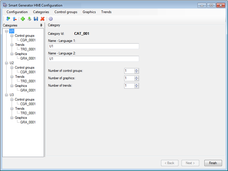
To add a new category, click in the category tree then the Add icon button in the menu. A new category, with default properties, is added to the end of the category tree. Category ID's are assigned automatically and cannot be edited. A maximum of 1000 categories can be created. The following properties can be edited:
Show picture-
Name - Language 1 - The identity of the category, if language 1 is selected, The name appears in the menu mimics at runtime. Up to 20 characters or ideograms.
-
Name - Language 2 - The identity of the category, if language 2 is selected, The name appears in the menu mimics at runtime. Up to 20 characters or ideograms.
-
Number of control groups - The number of control group mimics in the selected category. Range: 1..1000.
-
Number of graphics - The number of process mimics in the selected category. Range: 1..1000.
-
Number of trends - The number of trend mimics in the selected category. Range: 1..1000.
To delete a category, select it then click the Delete icon button in the toolbar. The category and all its mimics are deleted.
-
The order in which categories appear in the menu mimics at run-time is the same as configured in the categories tree. Be careful when adding or deleting categories as there are no specific tools to reorder them.
If you reduce the number of nodes below that were previously configured, a dialog warns you that related mimics will be deleted. Deleted mimics are moved to the project's sub folder \W\BAK.
-
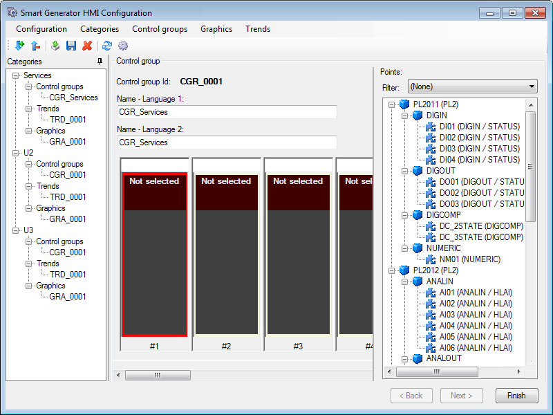
To add a new control group, select the node representing the category to which the control group is to be added then click Control groups in the main menu then Add control group. A new control group with default properties will be created with the following language properties:
Show picture-
Name - Language 1 - The name of the control group. If language 1 is selected, The name appears in the menu mimics at runtime. Up to 20 characters or ideograms.
-
Name - Language 2 - The name of the control group. If language 2 is selected, The name appears in the menu mimics at runtime. Up to 20 characters or ideograms.
-
-
To display the faceplate type and instance name, expand the tree structure of object PAS/POU in the right pane and select one of the eight faceplate (symbol) slots then double-click on the object's entry in the tree structure. Its faceplate type and instance name are shown in the slot's header and the next slot to the right is selected.
-
To add a new graphic, select the node representing the category to which the graphic is to be added then click Graphics in the main menu then Add graphics. A new graphic with default properties will be created with the following language properties:
-
Name Language 1 - The name of the graphic. If language 1 is selected, The name appears in the menu mimics at runtime. Up to 20 characters or ideograms.
-
Name Language 2 - The name of the graphic. If language 2 is selected, The name appears in the menu mimics at runtime. Up to 20 characters or ideograms.
To delete a graphic, select it then using the Delete icon button in the toolbar. The node is removed from the tree structure.
The HMI objects are designed for a display resolution of 1280x1024 pixels and for Full HDMI.
-
-
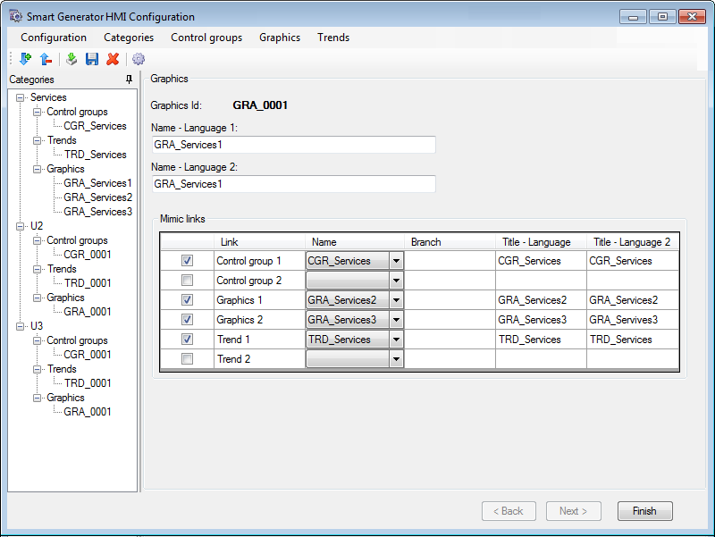
Pour configurer les liens vers les synoptiques, sélectionnez un graphique dans l'arborescence des Catégories. La configuration graphique est affichée dans le panneau de droite. Vous pouvez configurer des liens avec jusqu'à six autres synoptiques, deux groupes de contrôle, deux graphiques et deux tendances, au sein de la catégorie. Pour chaque lien, vous pouvez configurer les propriétés suivantes :
Voir l'image-
Lien - Si cette option est sélectionnée, elle active la configuration du lien.
-
Nom - Si spécifié, ouvre les noms du groupe de contrôle/graphique/tendance.
-
Branche - Si spécifié, définit la branche (s'il y en a une) pour le lien.
-
Description Langue 1 - Si spécifié, définit le texte qui apparaît sur le bouton au moment de l'exécution si la langue 1 est utilisée.
-
Description Langue 2 - Si spécifié, définit le texte qui apparaît sur le bouton au moment de l'exécution si la langue 2 est utilisée.
Par défaut, les deux liens pour les graphiques sont alimentés par les synoptiques précédent et suivant de la catégorie.
-
-
To add a new trend, select the node representing the category to which the trend is to be added then click Trends in the main menu then Add trends. A new trend with default properties will be created with the following language properties:
-
Name Language 1 - The name of the trend. If language 1 is selected, The name appears in the menu mimics at runtime. Up to 20 characters or ideograms.
-
Name Language 2 - The name of the trend. If language 2 is selected, The name appears in the menu mimics at runtime. Up to 20 characters or ideograms.
You must manually configure the Trend viewer after the Smart Generator has completed the generation. This is because each trend mimic created by the Smart Generator contains a single unconfigured Trend viewer.
-
Click Finish to complete the generation process.
Synchroniser un import existant
Lorsque vous synchronisez un import, le smart generator compare les éléments de configuration disponibles dans le fichier d'import avec ceux qui ont été importées précédemment dans PcVue.
La synchronisation tient compte des filtres que vous avez utilisés lors de l'import précédent. Par exemple, s'il y a 400 variables dans le fichier d'import et que l'import précédent était avec un filtre et avait créé 100 variables dans PcVue, la synchronisation vous informera qu'il y a 300 nouvelles variables à importer.
-
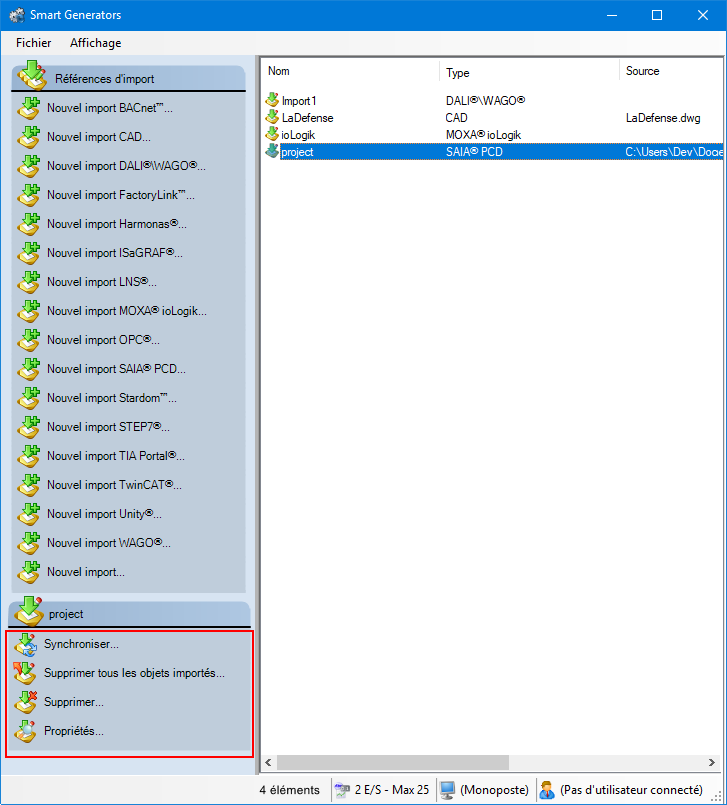
Sélectionnez l'import à synchroniser dans le panneau de droite de la boîte de dialogue des Smart Generators. Une liste avec des actions apparaît dans le volet Références d'import.
Voir l'image -
Cliquez sur Synchroniser. Cela ouvrira la boîte de dialogue du smart generator dans lequel vous pourrez reconfigurer l'import. Si des données ont été ajoutées dans le fichier d'import depuis le dernier import, le smart generator affichera la boîte de dialogue Import de nouvelles données vous invitant à effectuer soit un import complet, soit un import personnalisé des variables restantes.
-
Si vous sélectionnez Import complet, toutes les variables qui ne sont pas déjà dans PcVue sont importées.
-
Si vous sélectionnez Import personnalisé, vous serez en mesure de filtrer les variables en utilisant la boîte de dialogue Sélectionner les variables.
-
Si le smart generator détecte des variables dans PcVue qui ne sont plus dans le fichier d'import, la liste de ces variables s'affiche. En utilisant cette liste, vous pouvez choisir de supprimer de la configuration PcVue toutes les variables ou juste quelques-unes.
Vous pouvez choisir de ne supprimer que les éléments de configuration importés d'un smart generator sans supprimer l'import du smart generator lui-même. Cela peut être fait en faisant un clic droit sur l'import généré et en sélectionnant Supprimer tous les objets importés.
Stardom Library folder
The smart generator uses the Stardom Library to provide the specialized components for the HMI:
-
The Toolbox mimic.
-
Mimic templates.
-
Function key settings.
-
NPAS/POU symbols.
-
Global variable symbols.
-
Other symbols.
The Library folder for Stardom is stored in the PcVue library folder that by default is in the project sub-folder LIB. Here is a list of the files supplied in the library.
| Name | Subfolder | Description |
| Configuration files | ||
| STARDOMIMPORTCONFIGURATION.XML | TP | Includes Templates for all controllers, program instances and POUs as well as global definitions such as OPC groups. |
| STARDOMIMPORTCONFIGURATIONHMI.XML | TP | A list of configuration items that are to be created for each category (Control Group, Graphics and Trend). |
| Mimic templates | ||
| TPL_ALARMS | WT | For Alarm mimics. |
| TPL_CONTROLGROUP | WT | For Control Group mimics. |
| TPL_TRENDS | WT | For Trend mimics. |
| TPL_GRAPHICS | WT | For Graphics mimics. |
| TPL_MENU | WT | For Menu mimics. |
| TPL_SYSTEM | WT | For System mimics. |
| Template files | ||
| TOOLBOX.SIT | W | For Toolbox mimic. |
| TOOLBOX.SIT.BINARY | - | - |
| TRD_xxxx.SIT | W | For Trend mimics. |
| GRA_xxxx.SIT | W | For Graphics mimics. |
| CGR_xxxx.SIT | W | For Control Group mimics. |
| ALA_xxxx.SIT | W | For Alarm mimics. |
| SYS_xxxx.SIT | W | For System Overview mimics. |
| Mimics | ||
| MENU_CONTROLGROUPS | W | Including the Control Group menu. |
| MENU_GRAPHICS | W | Including the Graphics menu. |
| MENU_TRENDS | W | Including the Trends menu. |
| [POU Name]_Settings | W | Settings mimic. One for each supported POU. |
| Symbols | ||
| [POU Name] | S | POU symbol. One for each supported POU. |
| Images | ||
| [POU Name].png | B | Images of POU symbols to be used by the smart generator. |
| POU_GENERIC.png | B | Image to be used by the smart generator for POUs without an image of their symbol. |