Introduction
IEC 60870-5-104 (IEC104) brings standard TCP/IP communication to SCADA for power and utility systems—but it can feel unfamiliar if you’ve mostly used Modbus or OPC. With PcVue, establishing an IEC104 link is fast and straightforward. This guide shows how to go from zero to a Connected state in minutes, using the exact PcVue UI steps you’ll find in the Application Explorer.
What is IEC104 and why use it?
IEC104 is the TCP/IP variant of the IEC 60870-5 family and is widely used in electric utilities and grid automation for real-time telecontrol. It’s designed for secure, structured transfer of time-tagged measurements, commands, and status information between control centers and field equipment.
For engineers, IEC104 offers:
- Native TCP connectivity for WAN, fiber, and routed networks
- Standardized ASDU/IOA addressing for predictable mapping
- Strong support for time tagging, commands, and reporting
PcVue supports IEC104 natively, letting you connect, verify, and map data without dealing with low-level protocol complexity.
Setting Up Your IEC104 Device in PcVue
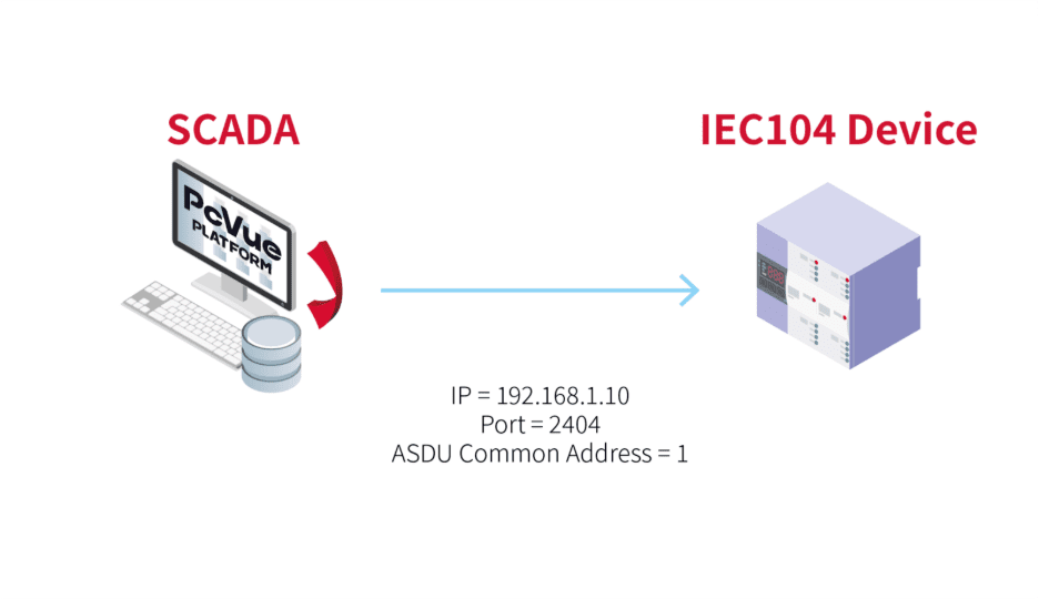
Step 1 – Gather Your Device Information
Before opening PcVue, collect a few essential parameters from your device. These are usually all you need for a successful connection:
| Parameter | Example | Description |
| IP Address | 192.168.1.10 | The IP address of your IEC104 device |
| Port | 2404 | Default TCP port for IEC104 communication |
| ASDU (Common) Address | 1 | The ASDU/CA assigned to the outstation |
💡 Tip: These values are usually in the device’s communications menu or vendor manual.
Step 2 – Create an IEC104 Network
DIn PcVue, communication is organized using Network objects. Networks group IEC60870-5 devices and define the communication context, which is especially helpful when you have multiple stations or distributed architectures.
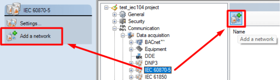
To add an IEC60870-5 Network:
- Open the Application Explorer.
- Expand Communication → Data acquisition → IEC 60870-5.
- Click the Add a Network button and give the new network a clear name (for example, “IEC104_Network”).
- Keep default settings unless you’re implementing multi-station setups.
The Network is your communication backbone — once created, add IEC104 Device objects underneath it. If you only run a single PcVue station, no extra configuration in the Network is normally required.
Step 3 – Configure the IEC104 Device
Once your Network is created, the next step is to add the actual IEC 104 device — this represents your field equipment.
- In the Application Explorer, navigate into the newly created IEC104 Network.
- Click the Add an IEC 104 device button.
- In the General tab:
- Enter the device’s IP Address.
- In the Advanced tab:
- Confirm the Port number (default: 2404).
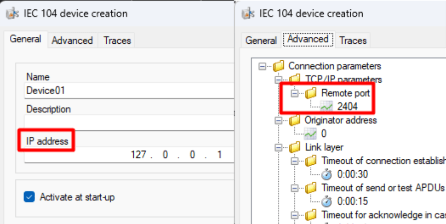
With this information PcVue will automatically attempt to connect to the device. If the parameters are correct, the device State should switch to Connected within seconds.
💡 Tip: At this stage, you don’t need to map any variables — seeing “Connected” confirms the TCP session.
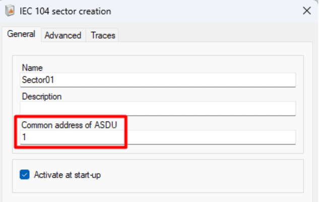
Step 4 – Add a Sector (required to see data)
A connected device gives you network-level communication, but PcVue needs a Sector to interpret and browse IEC104 data. You can think of it as the layer that tells PcVue which ASDU (Common Address) to associate with that device’s application data.
To add a Sector:
- In the Application Explorer, navigate into the newly created IEC104 Device.
- Click Add a Sector.
- In the Sector dialog, enter the device’s Common Address of ASDU (required).
Once the Sector is present and the ASDU is correct, mapping and browsing will show meaningful IEC104 objects (IOAs) in the Mapping window.
Step 5 – Verify and Troubleshoot Communication
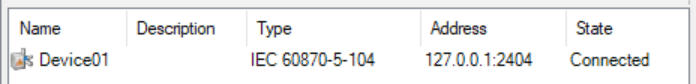
Once your IEC104 Device is configured, PcVue will automatically try to connect.
If the setup is correct, you’ll see the State column display “Connected.”
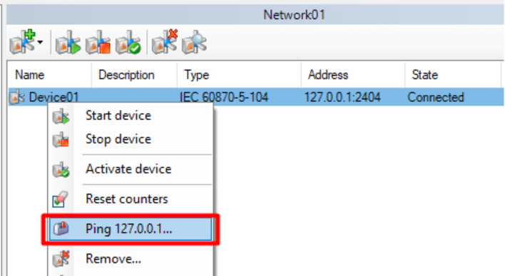
If it shows “Disconnected,” here are a few quick ways to check what’s going on:
- Ping the device:
- Right-click the IEC104 Device in the Application Explorer.
- Select “Ping XXX.XXX.XXX.XXX” to verify that the device is reachable
If the ping fails, check your network cabling, firewall, or IP configuration.
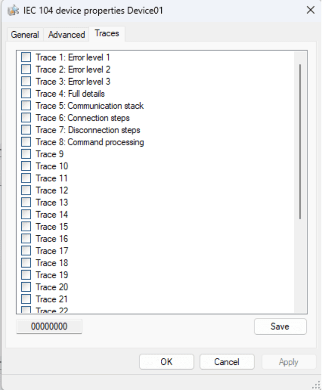
- View the Traces tab:
- Open the Traces tab in the Device configuration.
- Enable traces to generate detailed communication logs in the Event Viewer.
This helps identify connection issues such as mismatched link addresses or unreachable ports.
Usually, if the parameters in the General and Advanced tabs are correct, you’ll get a Connected state within seconds.
No further setup or variable mapping is required to confirm that your IEC104 communication is working.
Step 6 – Explore Your Data with Mapping
Once your device shows Connected, you’ve successfully established communication — congratulations!
The next step is to start visualizing or using your field data inside PcVue.
PcVue provides an intuitive Mapping tool to make this process simple.
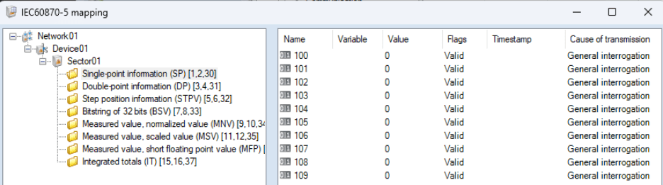
In the Application Explorer, select the IEC104 Network you created (or right-click on it), and choose Mapping.
This opens a browser window where you can explore the objects available in your IEC104 device — such as digital inputs, analog values, or counters — and link them directly to variables in your PcVue project.
You can:
- Map to new variables automatically created from the device’s structure.
- Link to existing variables already configured in your application.
- Filter or browse by object type to find exactly what you need.
Once mapped, these variables can be displayed in mimic diagrams, logged, or used in alarms — just like any other PcVue variable.
💡 Tip: You don’t need to complete this step to confirm your connection. Mapping simply allows you to take the next step: transforming raw data into actionable SCADA information.
Why PcVue Makes IEC104 Integration Simple
PcVue reduces the friction of IEC104 commissioning by combining a clear UI model (Network → Device → Sector → Mapping) with sensible defaults and built-in diagnostics:
- Native IEC104 driver — no middleware required.
- Minimal mandatory fields — IP, Port (Device), and ASDU (Sector).
- Quick diagnostics — Ping, State, and Traces help isolate issues fast.
- Scalable workflow — from one device in a lab to multiple devices across substations.
“With PcVue, IEC104 setup becomes as simple as entering an IP address and an ASDU.”
Discover PcVue’s full portfolio of communication drivers and supported protocols.
Conclusion
IEC104 gives you a standardized path to integrate field equipment over TCP/IP. With PcVue’s Network/Device/Sector model, only a few values are required to establish a working link and start mapping data. Start with one device, confirm Connected, add a Sector, and map the points you need.
Ready to explore IEC 104 in action?
👉 Check the Demo and test how easily you can establish a secure IEC 104 connection. Then follow our step-by-step video guide to walk through the configuration process with confidence Watch the video