How to import a CAD drawing
The Smart Generator for CAD allows you to import drawings and metadata from two of the most commonly available CAD file formats:
-
DWG - AutoCAD’s built-in format for storing 2D and 3D drawings and meta data in binary files.
-
DXF (Drawing eXchange Format) - Defined by AutoDesk Inc. for transferring CAD files between systems with different built-in formats, via ASCII encoded files.
Supported AutoCAD versions are: 12, 13, 14, 2000, 2004, 2007, 2010, and 2011.
The Smart Generator converts the contents of the CAD file into an image (WMF, JPG, BMP or PNG) and creates a mimic in which the image is displayed. This mimic is known as the primary mimic. Additional mimics (and corresponding images) can be created from the same CAD file showing different views, zoom levels, layers etc. These mimics are known as sub-mimics. Each time that you create a sub-mimic, a corresponding link-open animation is automatically generated in the primary mimic.
The CAD file components used by the smart generator are:
-
Layers - Each CAD drawing contains one or more layers. All drawing elements are attached to one of the layers (layer 0 by default). Each layer is given a color that is used when the CAD drawing is rendered. Layers can be hidden or shown to aid visualization. The contents of the layers are used to generate the image. The layers used can be filtered and they can be rendered in their original CAD colors or a single selectable color.
-
Block and Block references - A block is a group of drawing elements similar to a symbol in a library of PcVue. A block reference is an instance of a block similar to an instance of a symbol in a mimic. Blocks can be filtered to decide which instances of them (block references) will appear in the generated image. In addition, a block can be substituted by one of the PcVue symbol. Each block reference is then replaced with an instance of the symbol using a configurable variables branch.
-
Block attributes - A part of the definition of a block. They have a name and a value that may apply across all of their blocks of a particular type or to a single block. A block attribute is interpreted as a branch name for a symbol.
-
X-Refs - A reference to another CAD file. The X-Ref CAD files are used to provide additional detail for the main CAD drawing. For example, the main CAD file might show a building's structure whilst one or more X-refs might provide detail on services, lighting etc. X-refs can be filtered and selectively included in the generated image.
Refer to the overview topic Smart Generators overview to learn more.
Selecting the source data
-
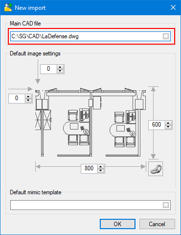
Go to Configure then Smart Generators and click New CAD import. The New import dialog opens.
 Show picture
 -
Click on the ellipsis button in the Main CAD file field and select a file with either a DWG or DXF extension.
-
Adjust the size in the fields on the right and below the drawing and adjust the position in the fields on the top left corner of the image. The mimic will be sized to fit the image if you are not using a mimic template.
You can use the Link icon button to retain the mimic's proportions when you set either the height or the width.
-
Click on the ellipses in the Default mimic template field to select a mimic template that has the standard look and feel you want to apply to the mimics created by the smart generator.
-
Click OK. The Smart Generator for CAD dialog opens and the primary mimic is created.
Navigating the main dialog of the Smart Generator for CAD
The main dialog of the Smart Generator for CAD contains several panes to manipulate the contents of the CAD file before it is imported into PcVue as a mimic. ![]() Show picture
Show picture
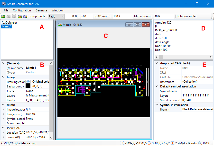
A - The top left pane lists the mimics that will be generated in PcVue from the CAD file. As a minimum, the primary mimic is listed. Sub-mimics created by zooming or cropping are also listed.
B - The bottom left pane displays the properties of the mimic that is currently selected. Some of the properties can be changed directly from here, for example, the layers that are displayed.
C - The center pane displays a representation of how the generated mimics will appear in PcVue. Each mimic is displayed in its own window. The Windows command on the menu can be use to change windows arrangement.
D - The top right pane is used when substituting CAD blocks with PcVue symbols and it displays the list of blocks that have been imported.
E - The bottom right pane is also used when substituting CAD blocks with PcVue symbols and displays the properties of the block that is currently selected. Some of the properties can be changed directly from here, for example, the symbol that is to be substituted for the block.
The toolbar is used to create and manipulate additional mimics (sub-mimics) based on the CAD file. Some of the tools are not displayed by default and must be first enabled by clicking Configuration main element then View. Here you can select the tools to display in the toolbar. The toolbar allows you to:
-
Create a new sub-mimic.
-
Save the configuration (zoom, crop, and rotation) of the CAD file within the selected sub-mimic.
-
Restore the original view of the CAD file within the selected mimic. Resets any zoom, crop or rotation operations.
-
Display a preview of the symbols.
-
Save the configuration of the CAD file within all mimics.
-
Changes the crop mode. There are two options: Free which allows any ratio of width (X) and height (Y) and Ratio which uses the width (X) and height (Y) ratio entered in the toolbar.
-
Define the zoom level and the rotation angle for the CAD file within the mimic.
-
Define the view zoom of the mimic.
The main menu gives you access to all of the usual buttons plus those specific to the Smart Generator for CAD such as the following:
-
Global filters accessed from the Configuration menu element. The purpose of Global filters is to display and apply filters to the Xrefs, layers and blocks of all sub-mimics. See the section Tuning the mimic below fore more information.
-
Windows - Change the way in which the windows containing the mimics are arranged. The following options are proposed: Cascade, Tile vertical, and Tile Horizontal.
Tuning mimics
After you have imported the CAD drawing and getting familiar with the workspace, the next step is to refine how you want the CAD drawing to be imported as a background image, and how you want the containing mimic to look like.
You can zoom, crop, and rotate the CAD drawing in the Smart Generator's display of the primary mimic, but this is only for convenience of viewing as you have already defined the visible area at the time of selecting the CAD drawing. It is not taken into account when the mimic is generated.
The same zoom, crop and rotate of the CAD drawing are used effectively when creating sub-mimics.
-
To control the CAD drawing, adjust the panning, zooming, cropping or rotating settings in the toolbar. If these settings are hidden, right-click on the toolbar and select the controls you would like to use.
You can also use your mouse to adjust the drawing:
-
To pan the CAD drawing (change its center relative to the center of the mimic), click and hold the right mouse button and drag.
-
To zoom the CAD drawing using the scroll wheel on your mouse. Rotating the wheel forward increases the zoom level, backwards decreases it.
-
To crop the CAD drawing, click and hold the left mouse button and drag the cursor. A dashed rectangle opens indicating the crop area. You can choose either Free cropping which allows any ratio of width and height or Ratio cropping which uses the width to height ratio entered in the toolbar.
-
To rotate the drawing, click on the center button and move the mouse to the right to rotate the image clockwise, or click the center button and move the mouse to the left to rotate the image counter clockwise.
-
-
To change the drawing color, click on the ellipsis button in the Drawing color field under Image in the left pane then select the new color. This new color is applied to all layers when image is generated. Typically in any CAD drawing, a different color is used for each layer.
-
To change the background color, click on the ellipsis button in the Background color field under Image in the left pane then select the color. The background color of a CAD drawing is often black, which may not be suitable for use in PcVue mimics. In many cases, the transparent color is what you want to take advantage of the mimic background color.
-
To select the layers displayed, click on the ellipsis button in Layers field under Image in the left pane then select the layers as required. These layers are displayed with only the visible layers being used when the image is generated.
-
To select blocks, click on the ellipsis button in Blocks under Image in the left pane then select the blocks as required. These blocks are displayed with only the visible blocks being used when the image is generated.
-
To configure the image size and location, adjust the image settings under Mimic in the left pane. The default image that is generated from the CAD drawing is sized so that it fills the entire mimic. Any space not occupied by the CAD drawing is filled with the background color. After you modify the image size the CAD drawing is automatically scaled to fit - you may then need to manually change this to suit your requirements.
You cannot change the image size or location of the image in the primary mimic.
-
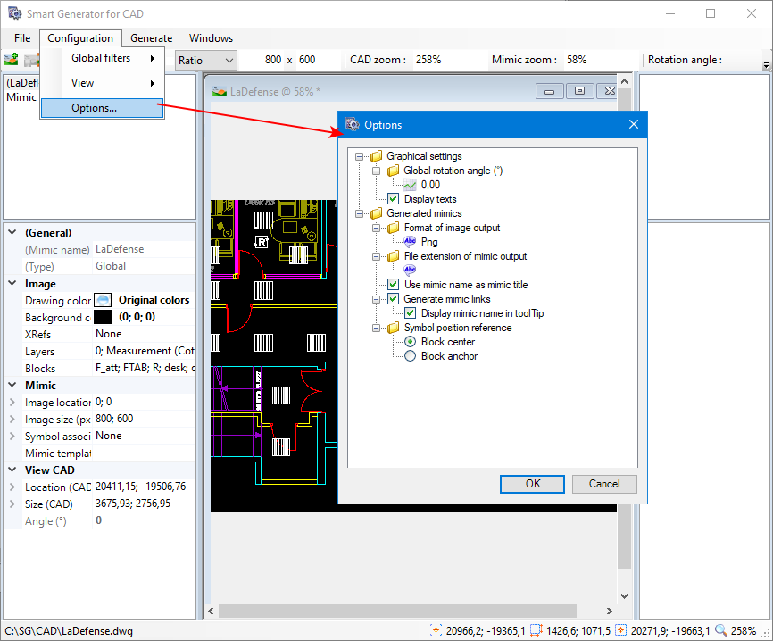
To configure the graphical settings for your CAD drawing, click Configuration from the main menu, then Options and set the Global rotation angle and Display texts properties as required.
Show picture -
To configure the generated mimics properties, click Configuration from the main menu then Options. Here you can set the following properties:
-
Generate mimic links - If specified, it generates the mimics links.
-
Display mimic name in tooltip - If selected, it provides tooltips to display the mimics names.
-
-
Symbol position reference - If specified, it defines where the reference of each of PcVue symbols is to be positioned. Either at the center or at the anchor of each block.
-
For image formatting properties, see Generating the mimics section below.
-
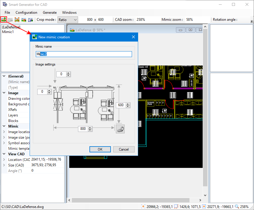
In addition to the primary mimic, you can also create sub-mimics by clicking and dragging the cursor to select the required part of the main drawing, then click the Create new mimic icon button on the toolbar. You are prompted to enter the name of the mimic and the size as well as location of the image. ![]() Show picture
Show picture
Substituting blocks with PcVue symbols
After configuring the mimics containing the configured CAD drawings, you can substitute CAD blocks with PcVue symbols before generating the mimics. When the mimics are generated, each block reference is replaced by an instance of the symbol and an optional branch. The symbol is overlaid on the image at the position of the original block reference.
-
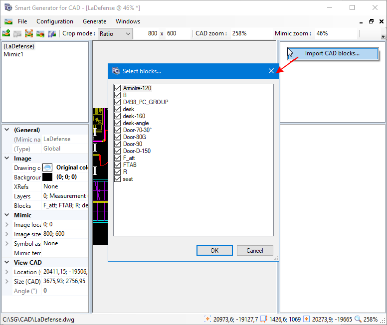
To substitute CAD blocks with PcVue symbols, right-click in the top right pane of the Smart Generator for CAD dialog and select Import CAD blocks from the pop-up menu. A dialog opens displaying the list of blocks available in the drawing.
Show picture -
Deselect those blocks that are not to be substituted by one of the PcVue symbols, then click OK to close the dialog. A list of the selected blocks is now displayed in the top right pane.
You can deselect all the blocks by right-clicking and selecting Uncheck all from the pop-up menu.
-
Select one of the blocks listed from the selected block's properties in the bottom pane, click on the ellipsis button in the Symbol name property. This opens a dialog displaying a list of PcVue symbols to choose from to replace the block. Select the symbol to use for the selected block and click OK.
-
To change the mimic layers in which the symbol is to be visible, modify the Layers property. By default, a symbol will be visible in all layers.
-
To change the visibility bound which is the mimic zoom level at which the symbol is visible, modify the Visibility bound property. The default behavior is that a symbol is visible throughout the PcVue zoom range.
-
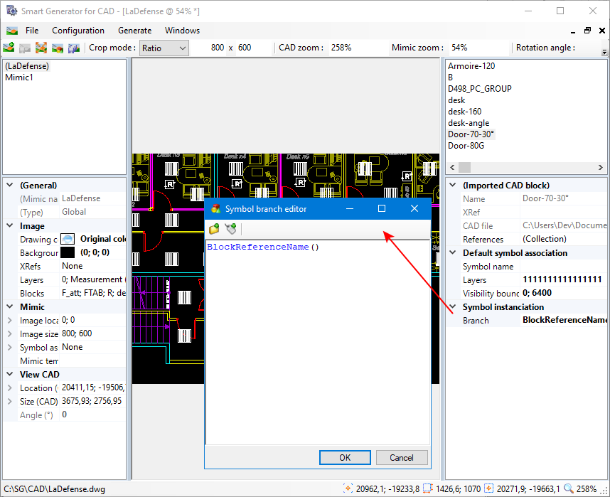
To add a branch to be used with all instances of the symbol, click on the ellipsis button in the Symbol instantiation property. The Symbol branch editor opens.
Show pictureThe branch is entered as an expression that can contain the following elements:
-
Fixed strings - These strings must be enclosed in quotation marks. For example "BUILDING_01.".
-
Variable branches - Selected from the variables tree using the Add a branch icon button. These branches become fixed strings in the expression.
-
Block attributes - Any of the CAD block's attributes entered as Attribute("Name"). For example Attribute("NUMBER"). They can be added using the Add an attribute icon button.
-
BlockReferenceName - The reference name of the CAD block.
-
Functions - A mathematical or string function. For example StrToLower. Functions can be typed or selected from a context menu that is displayed using the key combination Ctrl+Space.
-
Operators - An operator such as + (addition or concatenation depending on the context).
For a complete list of functions, see the topic Expression Engine Overview.
-
-
To configure the individual block references, click on the ellipsis button in the References property under Imported CAD block. The References editor dialog opens. The left pane contains a list of the block references and the right pane contains the properties of the selected block reference.
-
Deselect those block references that are not to be substituted by one of the PcVue symbols. You can deselect all the blocks by right clicking and selecting Uncheck all from the pop-up menu.
-
Select each of the selected block references in turn and click on the ellipsis button in Branch field to configure the variables tree branch to be used with the instance of the symbol for that reference then click Close. The branch is constructed by concatenating the Inherited branch with the Branch property. The branch is entered as an expression (See step 6).
When you select a reference in the References editor, a white rectangle opens around the corresponding block on the map. Conversely, when you click on a block's position on the map, its reference is highlighted in the Reference editor's list.
-
To change the symbol used for a particular mimic, expand the Symbol associations property under Mimic in the bottom left pane and select the symbol, layers, and zoom level. The default behavior when substituting a block with one of the PcVue symbols, the substitution applies to all mimics that are generated from that CAD drawing.
Generating the mimics
Generating the mimics is the final step of the CAD drawing import process. For each mimic a corresponding image is generated.
-
Click Configuration from the main menu then Options. Here the following properties should be configured as they affect the generated output:
-
Image format - The format in which the image is generated. The following are available:
-
WMF & EMF - If selected, it generates the images at the same resolution as the original CAD drawing and then scales them to fit the specified size. No loss of detail but can generate very large files. Transparent background color is supported.
-
BMP - If selected, it generates the image at the specified size, so this has considerable potential for loss of detail. It generates a medium sized file. Transparent background color is supported.
-
JPG - If selected, it generates the image the specified size so this has considerable potential for loss of detail. It generates a small file. Transparent background is not supported.
-
PNG.
-
-
File extension of mimic output - If specified, it defines the file extension to be added to the name of the generated mimic file. The default is none.
-
Use mimic name as mimic title - If selected, it generates the mimic with the same title as the mimic file name, shown in the title bar.
-
Display texts - If selected, it renders any text strings that appear in the original CAD drawing in the image that is produced.
-
-
Click Generate from the main menu then Generate mimics. If you have not saved your recent changes, you are prompted to do so then the Select targets to generate dialog opens.
-
Deselect any mimics that are not to be generated then click OK to start the generation. A progress dialog is displayed. Click Close when it is done generating.
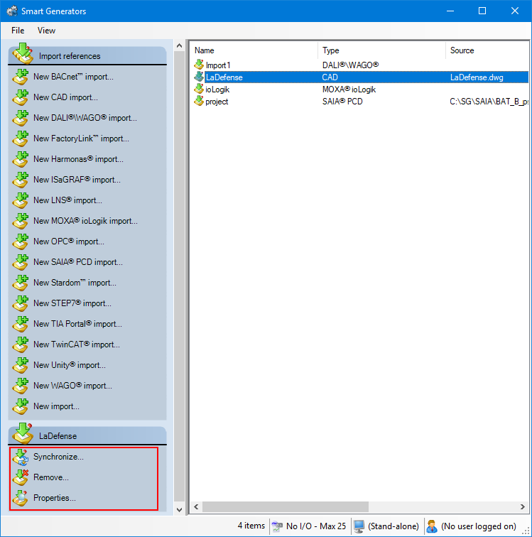
Synchronizing an existing import
When you synchronize a CAD drawing, the smart generator updates the drawings contained in the mimics imported into PcVue.
-
Select the CAD import to synchronize from the right pane of the Smart Generators dialog. A list with actions appears under the Import references pane.
Show picture -
Click Synchronize. This will open the smart generator dialog in which you can reconfigure the import. The smart generator remembers all of your previous configurations to the drawing. All you have to do is update the drawing and select Generate from the main menu then Generate mimics to synchronize. For example if you add three new blocks to the drawing, the smart generator generates three more symbols in the appropriate mimic.