How to import a Siemens FactoryLink configuration
The Smart Generator for FactoryLink allows you to import a FactoryLink project from which it generates the following PcVue configuration elements:
- Variables including array variables, alarms, historical, OPC and Modbus configuration.
- Data acquisition for the OPC-DA client (OPC servers and OPC groups).
- Mapping of variables onto OPC configuration elements. Only if you intend to use the FL OPC server with PcVue.
- Math and logic procedures. Copy only - no automatic conversion.
- Mimics and mimic templates.
- Local library (symbols and images).
- Shared libraries (symbols and images). Imported as PcVue global libraries.
This version of the Smart Generator can only import project files generated with version 7.5 of FL.
The FL version 8.0 format of the file MLANG.DAT is supported.
Differences between the FactoryLink animation engine and PcVue
There are some differences between FL Client Builder and PcVue in regard to the animation engine:
-
Color on register level animation - There is an option in Client Builder (Ignore animation when less than) that has no effect in PcVue.
-
Bit animation - In a Client Builder bit animation (such as Color on Bit), you can configure a register variable instead of a bit variable. This is not supported by PcVue, so it creates an expression instead. If any register variables are found, they are replaced with the expression. For example =TANK1.LEVEL != 0.
-
Client Builder clusters - Some Client Builder tags may be prefixed with the cluster name. Before import, the smart generator reads the Client Builder file SERVERS.DAT. The list of cluster names enables it to resolve the expressions. The smart generator removes the cluster name. For example =OPCcluster:A_YEAR - OPCcluster:A_DAY becomes =A.YEAR - A.DAY.
-
OPC array items - Client Builder uses two different syntaxes to address array items. For example TASKSTART_S[10] and TASKSTART_[10]_S refer the same OPC array item (TASKSTART_S). The Smart Generator is able to handle the two syntaxes so as to create as many variables as there are array elements and adapt animation configuration.
-
Send eSignature animation - The Client Builder animation eSignature has no equivalent in PcVue. A warning is displayed when opening a mimic containing this animation and it is removed from the mimic.
-
Windows metafile support (.WMF) - Client Builder and PcVue do not handle Windows metafile graphic files in the same way. However, the smart generator processes any imported .WMF file so that it has the same appearance as in Client Builder.
-
Client Builder supports multiple languages and roles. By default, it is configured to support three languages, English, French and German, and four roles, Administrator, Supervisor, Operator and Other. Wherever you can enter text in Client Builder, you can enter a string for each of the roles for each of the languages making a potential for up to 12 strings for each text. PcVue supports texts for two languages and does not support roles, so when importing the mimics from Client Builder you specify which Language/Role combinations you want to import
Prerequisites
-
You have installed the FL application on the same machine as PcVue.
-
You have converted the project's mimic and symbol files into ASCII format. If not, you an use the FL Client Builder's Library Converter to do so. For ECS elements, you must first convert the graphics to Client Builder using ECSCONVERT, a tool in the FL package.
Refer to the overview topic Smart Generators overview to learn more.
Selecting the source data
Before you start the import process, we recommend that you back up the PcVue variables configuration in case of any problems occurring during the import process. The variable configuration is stored in the file VAREXP.DAT in the project's C folder.
Make sure that PcVue is shut down before copying the file.
-
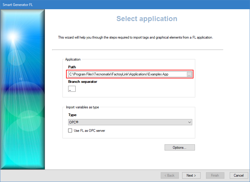
Go to Configure then Smart Generators and click New FactoryLink import. The Smart Generator FL dialog opens.
 Show picture
 -
Enter or select the path to the FL application folder in the Path field.
-
Enter the branch separator used in the FL application (defaults to '_'). It is replaced by the PcVue branch separator '.'.
-
Select how variables will be imported, either as Internal variables or as OPC variables. If you select OPC in the Type field, you can tick the Use FL as OPC server box. This automatically configures the OPC Server, OPC Group, and OPC Item name in the variable mapping when importing to PcVue.
Using FL as OPC Server offers a smooth migration path. It allows you to migrate the HMI part first, phase during which you continue to use FL as data acquisition server, and PcVue as HMI. You can then migrate the data acquisition part of your system.
-
Click the Advanced/Options button, then select a server list and a client list in the Networking list tab to define the behavior of PcVue variables for a multi-station project.
The lists of servers and clients must already have been created in PcVue and the station from which you run the smart generator must be in the servers list.
-
Select the Options tab in the Options dialog. Here you can configure all the options affecting the import of configuration elements other than the HMI:
Properties Description FL Tags The following options are available for FL tags:
-
Import "SHARED" tags only - If selected, it imports tags that share a common value on a multi-station application.
-
Import "USER" tags only - If selected, it imports tags that do not share a common value on a multi-station application.
-
Import both "SHARED" and "USER" tags - If selected, it imports both tags that share a common value on a multi-station application and those that do not.
Variables default values The following options are available for Variable default values:
-
Initialize internal bit tags to zero - If selected, it sets the option in PcVue to initialize internal bit variables to a value of 0.
-
Import tags with default values as saved variables and generated persistence file - If selected, it sets the option to save variables so that their value is maintained through a shutdown and restart. Creates the corresponding persistence file.
Domains The following options are available for Domains:
-
Generate USER and SHARED domains - If selected, it creates the USER and SHARED domains and adds the relevant domain to each of the imported variables.
Arrays The following options are available for Arrays:
-
Array formats - If selected, it controls the way in which the array index is converted to the branch via the following properties:
-
Standard arrayname.[dimension 1]...[dimension n]. For example in PcVue PUMP.STATUS.1
-
Reversed [dimension 1]...[dimension n].arrayname. For example in PcVue 1. PUMP.STATUS
-
-
Import multi-dimensional arrays - If selected, it allows the import of arrays with more than 1 dimension. The maximum theoretical number of dimensions is 5 (PcVue variables can have a maximum of 6 elements).
-
Add a leaf variable for a standard format array - If selected, it adds a specified leaf (final element) to the generated variable name. For example PUMP.STATUS.1.VAL. This is useful when you want to use the array variables in a symbol. The leaf is referenced within the symbol and the remainder of the variable name used as the branch when the symbol is instantiated.
FL allows the use of single and multi-dimensional array variables in its projects. As array variables are not supported by PcVue, when an array variable is imported the array index is converted to a variable branch. For example, a single dimensioned array in FL called PUMP_STATUS might be converted to the variables PUMP.STATUS.0, PUMP.STATUS.1 etc. in PcVue.
Alarms The following options are available for Alarms:
-
Import alarms - If selected, it enables the import of alarms.
-
Log alarm transitions - If selected, it sets the Log to 0 and Log to 1 properties of the generated bit variables so they are eligible to be logged.
-
Generate a domain for each alarm group - If selected, it generates a Domain for each FL alarm group.
-
Import alarm descriptions - There two options to choose from:
-
Import FL tag description as alarm description.
-
Import FL alarm message as alarm description.
-
-
Import alarm status - If selected, it imports the alarm status.
-
Import alarm mask - If selected, it enables the import of alarm mask.
-
Import analog alarms as - There are three options to choose from:
-
Expressions only - If selected, it creates an expression and bit for each alarm condition.
-
Thresholds bit variables only - If selected, it creates a register variable with thresholds for each alarm condition.
-
Expressions or thresholds variables, depending of the alarm condition - If selected, it creates an expression and bit, or register with thresholds as applicable to the alarm condition.
-
See the example below to learn more about how alarms are imported.
The FL Smart Generator generates additional properties when importing alarms. These properties are:
-
A domain for each alarm group.
-
The alarm label in attribute 3 of the generated variable.
-
The variable that represents the condition in the attribute 5 of the generated variable.
-
The alarm group name in attribute 4 of the generated variable.
-
Alarm level (depending on the FL alarm's Priority).
-
Alarm mask (depending on the FL alarm's Hide tag).
-
Alarm acknowledgment bit (depending on the FL Alarm Status tag).
Historical The following options are available for Historical:
-
Import Datapoint Logging as proprietary archiving - If selected, it imports the logging as trend recording in a proprietary archive unit.
-
Import Database Logging as proprietary archiving - If selected, it imports the logging as trend recording in a proprietary archive unit.
For example, in a table in which three FL tags are logged and the database alias name is MYDPLOG, the Smart Generator generates a proprietary archive unit MYDPLOG with the corresponding trend elements that can be found in Archive units node in the Application Explorer.
OPC configuration The following options are available for OPC configuration:
-
Import OPC client configuration - If selected, it imports configuration elements for OPC communication, irrespective of the types of variables to be generated (OPC or internal).
-
Import ODX OPC configuration - If selected, it imports configuration elements for ODX (OPC Data eXchange). The import process is similar to that for OPC.
For example: Consider a configuration with three OPC server aliases: DIDI_IN, DIDI_OUT and FS. The FS alias represents a local ModbusExplorer OPC Server. An OPC group, GR1, has been configured. Attached to group GR1 are two FL tags mapped on the same OPC item ID. From this, the Smart Generator generates:
-
Three OPC servers and their associated OPC groups which appear in OPC in Data acquisition node in the Application Explorer.
-
OPC variables which appear in the source tab of a variable if the OPC server is selected.
Device configuration elements The following options are available for Device configuration elements:
-
Import Modbus TCP/IP configuration - If selected, it imports the FL configuration for the Modbus Ip driver. There are two equipment type options: JBUS_DEC and MODBUS_DEC.
-
Import GE TCP/IP configuration.
-
Import Telemecanique configuration as Modbus Ip.
-
Import Scaling configuration.
IML The following options are available for Math and Logic:
-
Generate SCADA Basic skeleton according to IML - If selected, it formats each procedure as a skeleton SCADA Basic program with a copied body as follows:
-
The SUB command.
-
The IML code, with each line marked as a comment.
-
The ENDSUB command.
-
-
Import IML trigger variables as EVENTS or CYCLICS - If selected, it imports each IML trigger tag as an Event or Cyclic action, depending on the nature of the trigger tag.
For details of their effects in PcVue, refer to the Event actions sub-book and the Cyclic actions sub-book for more information.
-
Copy math and logic procedures to project program directory - If selected, it copies the IML procedures to the program directory of your project.
See the section below to learn more about how IML procedures are imported.
FL's Interpreted Math & Logic procedures are similar to PcVue SCADA Basic programs. Many Math and Logic procedures can be converted to SCADA Basic via a manual process. To assist with this, any Math and Logic procedures found by the Smart Generator are processed as follows:
-
Shared procedures are copied to the Math and Logic (SHARED) sub-folder of the projects P folder.
-
User procedures are copied to the Math and Logic (USER) sub-folder of the projects P folder.
-
The files (FLPROCS.DAT for SHARED and FLPROCU.DAT for USER) are generated. These contain one line for each procedure containing the tag, procedure name, and (optional) comment.
Advanced The following options are available for Advanced:
-
Import report configuration - If selected, it imports report templates from the FL project. This generates a file containing the list of aliases and the corresponding variables in PcVue and a VBA module that enables you to generate the report. The report file is generated in project folder C and named IMPORTREPORT.TXT.
-
Generate a CSV file containing imported tag names before and after import (FLImport\renamed_variables.dat) - If selected, it creates a CSV formatted file containing, for each of the tags, the original FL tag name and the name of the corresponding variable in PcVue. Not used by the application but a useful reference for debugging after the import.
-
Understanding how FL alarms are imported
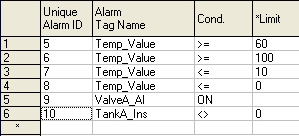
Consider the following Alarm Definition Information dialog from an example FactoryLink configuration. ![]() Show picture
Show picture
-
FL alarm using a digital tag - VALVEA_AL is a FL digital tag. The Smart Generator generates the Bit variable BIT VALVEA.AL with the Alarm property set. The alarm will be configured to be active when the value is 1 as determined by the Condition having a value of ON.
-
FL alarm using an analog tag (as an expression) - TANKA_INS is an analog tag. It is configured to produce an alarm when its value is NOT 0. The Smart Generator creates an expression TANKA.INS != 0 attached to the new Bit variable TANKA.INS_NE_0. The bit will have the Alarm property set and be configured to be active when the value is 1.
-
FL alarm using an analog tag (as a threshold) - TEMP_VALUE is an analog tag and appears in four alarm conditions. The Smart Generator creates a new register variable TEMP.VALUE with a threshold value for each condition.
Understanding how FL math and logic procedures are imported
The Smart Generator can create a SCADA Basic program TempProg containing the corresponding IML procedure in comments as follows:
sub TempProg()
' proc TempProg
' begin
' if Temp_Value > Temp_SetPoint then
' Temp_Value = Temp_Value - 1
' endif
'
' if Temp_Value < Temp_SetPoint then
' Temp_Value = Temp_Value + 1
' endif
' end
end sub
It can also create an Event or Cyclic called TempProg to trigger it. After import of the FL application, you would rework the program into SCADA Basic as follows.
sub TempProg()

if ( Temp.Value > Temp.SetPoint) then
Temp.Value = Temp.Value - 1;
end if

if (Temp.Value < Temp.SetPoint) then
Temp.Value = Temp.Value + 1;
end if

end sub
The Smart Generator creates new files listing the procedures (FLPROCS.DAT for SHARED and FLPROCU.DAT for USER) then creates the corresponding program files.
Here is an example of PROCS.DAT contents (tag; procedure; description).
IM_Lotstart[1];IM_Lotstart1;IM Lotstart procedure

IM_Lotend[1];IM_Lotend1;IM Lotend procedure

IM_Lotend_Rpt_Comp[1];IM_Lotend_Reset1;IM Reset Lotend

MM_Lotstart[1];MM_Lotstart1;MM Lotstart procedure

MM_Lotend[1];MM_Lotend1;MM Lotend procedure

MM_Lotend_Rpt_Comp[1];MM_Lotend_Reset1;MM Reset Lotend

TM_Lotstart[1];TM_Lotstart1;TM Lotstart procedure

TM_Lotend[1];TM_Lotend1;TM Lotend procedure

TM_Lotend_Rpt_Comp[1];TM_Lotend_Reset1;TM Reset Lotend
After the import, the procedure files (.PRG) are accessible along with the FLPROCS.DAT file in the sub-folders of the P folder.
Defining the arrays and selecting variables
After importing and configuring the networking list and options of the import via the Select application dialog, the next step is to define the arrays and select variables.
-
Click Next, the Array Format dialog opens. Here the arrays configured in the FL project are listed. Select arrays for which you want to choose the import format according to the Client Builder configuration (with index before or after the array name), then click Change Format button. You can also deselect arrays to exclude from the import list.
-
Click Next, the variable import process is initialized and the Select import type dialog opens. Select the type of import you need:
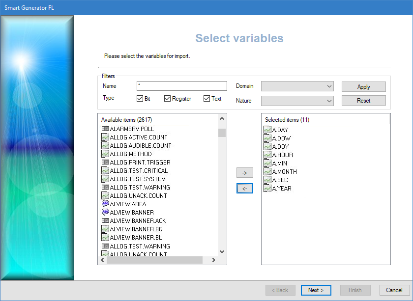
- Custom import if you want to access the Select variables dialog in which you can filter and manually select the list of variables to import.
- Full import if you want to generate variables for all source data.
-
(Custom import option) Adjust the filters to find the variables to import. The Name field allows to filter the list of variables according to the name in the source data. You can use wildcards, the asterisk (matches any number of characters) and the question mark (matches a single character).
For example:
'Pump1' would only match a source data named 'Pump1'.
'Pump?' would match 'Pump1' or 'Pump2' etc. but not 'Pump10'.
'Pump*' would match 'Pump1', 'Pump2' and 'Pump10' but also 'Pumpkin'.The variables that match the filter appear in the Available Items pane.
-
(Custom import option) Select the variables filtered in the Available items pane for import and click the right-arrow -> button. The variables in the Selected items pane are to be imported and generated.
Renaming and generating variables
After you have defined the branch and selected variables to generate via the Select variables dialog, the next step offers the possibility to edit the variables you have selected and prepare them for generation.
If a variable is displayed in red, it means that it is invalid for use in PcVue and will not be generated. Use the Rename variables dialog to ensure variable name compliance:
- The max length of a variable name is 255 characters.
- The max number of branch elements in a variable name is 12.
- The name of a branch element or the name of the leaf element cannot be empty (length =0) or exceed 255 characters.
- The name of a variable can only include letters, digits, or the underscore.
- Variable names shall be unique. Two variables cannot have the same name.
After defining the arrays and selecting variables to generate via the Select variables dialog, the next step is to edit the variables selected and prepare them for generation.
-
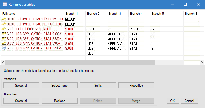
Click Next. The Generate variables dialog opens, listing all variables selected for generation. To rename variables, either select variables and click Rename selected, or use the Rename invalid button. The Rename variables dialog displays variables in a grid and offers several actions.
-
The Rename variables dialog is designed to make it easy to give a final polish to variable names and fix invalid ones, and also to bulk modify variable properties, to set the Command level or Alarm property for example.
The following operations are available:
- To modify a single variable, double click it, or select it and click Properties. You can edit its name in the General tab. Click OK to validate.
- To add a leaf to one or more variables (to add a .Cmd or .AlarmTmpHigh for example), select them, then click Suffix and enter the suffix to be added. Click OK to validate.
- To replace characters in the name of one or more variables, select them, then click Replace to open the Replace dialog. Enter the strings to search and replace, then click OK.
- To replace branch segments, select the variables, then select the branch segments to be replaced by clicking on the column header and click Replace to open the Replace dialog. Enter the strings to search and replace, then click OK.
- To delete a branch segment, select the variables, then the branch segments to be removed by clicking on the column header and click Delete. The selected branch segments are then removed from the selected variables.
- To merge branches, select the variables, then the branch segments to be merged by clicking on the column header and click Merge. The selected branch segments are then deleted for the selected variables. You can only merge consecutive branch segments.
You can edit the variable properties in the Details tab. These properties can be its type, domain, nature etc.
You can use Shift+click to select a group of adjacent variables and branches or Ctrl+click to select several individual variables.
Once you are done editing the variables click OK to close the dialog.
To avoid conflicts, if there is a FL tag named TIME, USER or DATE, the smart generator will automatically rename the variable concerned to FLTIME, FLUSER or FLDATE.
-
Click the Finish button to import the variables only or click Next to import mimics or symbols from the Client Builder elements. If you click Finish button, any variables in the smart generator that already exist in PcVue are discarded. The corresponding variables in PcVue are not overwritten or updated in any way.
Any variables appearing in red are invalid and will not be generated when clicking Finish.
Importing graphics
After renaming variables and defining their overall structure via the Rename variables dialog, the next step is to import symbols, images, and mimics.
The Smart generator can only import mimics and symbols saved in ASCII format. You can convert mimics and symbols to ASCII format in bulk using Client Builder's Library Converter (menu Display\Library converter).
-
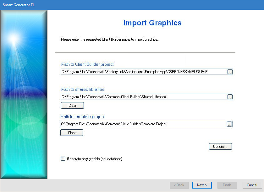
Click Next, the Import Graphics dialog opens. Here you can configure the import of mimics, symbols, and images contained within a Client Builder project, shared libraries, and template project.
Show picture -
Click on ellipses button in the path fields and go to the folder where the Client Builder project (.FVP), shared libraries, and template project are located and select them individually.
The files are processed and copied to:
-
The Client Builder project is copied in the PcVue project.
-
The Client Builder shared libraries are copied into the PcVue shared libraries.
-
The Client Builder project template folder is copied into the PcVue root folder TPL.
-
-
Click on the Options button. The Languages tab opens. Select which Language/Role combinations you want if you are importing from a multilingual project. If you do not select a language or role, the default setting imports the English/Administrator strings for both languages. You should ensure that Client Builder text has been filled in for the languages chosen. If not, the imported text will be empty in PcVue.
If you want to import strings for two languages you must enable PcVue bilingual text strings option from Languages dialog opened from Configure in the main menu, then Project Settings. Restart before starting the import.
-
Select the Options tab. Here you can select or deselect the Client Builder elements you would like to import via the following properties:
-
Import mimics - If selected, the Smart Generator imports mimics from the Mimic Files folder.
-
Import symbols - If selected, the Smart Generator imports the symbols from the Symbol Files folder.
-
Import images, AVI etc. - If selected, the Smart Generator imports all images from the Image Files folder. Some images may be licensed only for use with FL and therefore must not be used with PcVue. Make sure to check before you enable this option.
-
Import options - If selected, the Smart Generator imports FL configuration options.
-
Do not import VBA scripts - If selected, the Smart Generator does not allow the import of VBA scripts.
-
Import VBA scripts - If selected, the Smart Generator imports VBA scripts.
-
Import and comment VBA scripts - If selected, the Smart Generator imports VBA scripts but each line is commented out so that the scripts can be systematically reviewed before they are enabled.
-
Copy "Config Files" content to "C" folder - If selected, the Smart Generator copies the contents of the Client Builder Config Files folder to PcVue C folder. Although this option copies files such as the color palette, some files will be overwritten when PcVue shuts down. Client Builder files for which there is no equivalent in PcVue are not copied (for example SERVERS.DAT and SECURITY.DAT).
-
Rework files during import - If selected, the Smart Generator rework files during the import process by renaming variables etc.
To import the Client Builder color palette if the project uses any indexed colors (the 32 colors found in the lower half of the color palette), the PALCOL.DAT file which contains the color palette must be manually copied from the Config Files folder of the Client Builder project to the C folder of the PcVue project before you change or use any of the default colors in the PcVue palette.
PcVue must not be running when you copy the file, since it would overwrite the file when it is next shut down.
-
-
Click OK to close the Options dialog.
-
Tick the option Generate only graphics if you want to import the graphic elements only (and not the variables).
-
Click Finish to proceed with the import.
The smart generator is able to convert both primary and secondary variables. For example, for a Send Register animation there is one primary variable and up to six secondary (optional) variables.
If you import shared libraries, the file LIBRARY.DAT is updated. If an entry is already present in the LIBRARY.DAT file, a similar entry is not appended to it.
If a symbol is contained in a mimic, this process is transparent. For instance, a symbol from the folder Shared Libraries\MySpecialLib will be copied to the folder Lib\MySpecialLib then processed.
The destination folder for template project is TPL rather than USR\[Project Name].
Image, video, audio etc. media files are copied to the destination folder corresponding to the FL source folder. You must ensure that their formats are compatible with PcVue.
By default, background schematics are generated as GIF files.
If you choose not to import animation-related variables from FL, you must ensure that there are variables in PcVue with branch structure and names corresponding to those required in the animations in the graphic elements derived from FL.
Synchronizing an existing import
When you synchronize an import, the smart generator compares the configuration elements available in the import file with those that have been imported previously to PcVue.
The synchronizing process takes into account any filter that you may have used previously with the import. For example if there are 400 variables in the import file and the previous use of the import was with a filter and created 100 variables in PcVue, synchronization will inform you that there are 300 new variables available for import.
-
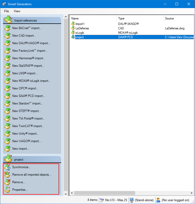
Select the import to synchronize in the right pane of the Smart Generators dialog. A list with actions appears under the Import references pane.
Show picture -
Click Synchronize. This will open the smart generator dialog in which you can reconfigure the import. If variables have been added to the import file since the last import, the smart generator will display the Import new variables dialog, inviting you to make either a full or a custom import of the remaining variables.
-
If you select full import, all variables not already in PcVue are imported.
-
If you select custom import, you can filter the variables using the Select variables dialog.
-
If the smart generator finds variables in PcVue that no longer exist in the import file, a list of the variables is displayed. Using this list, you can choose to remove some or all of the variables from PcVue.
You can choose to only remove imported configuration elements of a smart generator without removing the smart generator import itself. This can be done by right-clicking the import generated and selecting Remove all imported objects.
FactoryLink import report
A report file named IMPORTREPORT.TXT is generated in the project folder C. The following is an extract of such a report.
Importing project "C:\Program Files\FL\Applications\Examples App\CBPROJ"
Importing mimics...
-------------------
Warning: file D:\100\USR\T4\W\s1 is not ASCII format
Number of mimics processed : 10
Importing mimic templates...
----------------------------
Number of mimic templates processed : 1
Importing symbols...
---------------------
Warning: file D:\811\USR\T4\S\tp1 is not ASCII format
Warning: file D:\811\USR\T4\S\ tp2 is not ASCII format
Warning: file D:\811\USR\T4\S\ tp3 is not ASCII format
Warning: file D:\811\USR\T4\S\ tp4 is not ASCII format
Warning: file D:\811\USR\T4\S\ tp5 is not ASCII format
Number of symbols processed : 29
Importing images...
-------------------
Number of images processed : 40
Generated configuration elements references
Many configuration elements are generated during the import process. The tables below describe property values for OPC data acquisition elements and variables.
OPC configuration
The OPC server properties are configured as follows.
| Properties | Value |
| Alias | Default value: SERVER. |
| Network Node | Default value: empty (local machine). |
| Server PROGID |
FL.OPCServer.1 or FL.DevOPCServer.1 if FL is used as an OPC Server, else unused. |
|
Active at launch |
True |
The OPC group properties are configured as follows.
| Properties | Value |
| Alias | Default value: GRP1. |
| Scan Rate | Default value: 1 second. |
| Active at launch | True |
Variables configuration
The variable properties are configured as follows.
| Properties | Value |
| Name |
The default value is based on the FL tag name but you can modify that name during import. |
| Branch | According to the branch separator. |
| Domain | Optional, depending of the FL domain or alarm group. |
| Description |
This can be optionally derived from the FL tag description or from the alarm message. |
| Source |
OPC or Internal (import option). Equipment when importing Modbus TCP configuration. |
| Alarm | Depending on FL tag. |
| Alarm Level | Depending on FL alarm Priority. |
| Alarm Mask | Depending on FL alarm mask tag. |
| Alarm Ack bit | Depending on FL alarm Status tag. |
| Command | True. |
| CommandLevel | 0. |
| Variable type |
Variable type correspondence between FL and PcVue.
|
| Min / Max |
FL Variable range.
|
| Attribute3 | FL alarm message text. |
| Attribute4 | Alarm group name. |
| Attribute5 | Name of the variable for the alarm. |
| Server List | Optional, user-provided. |
| Client List | Optional, user-provided. |
| Min |
According to the FL tag default value tagname.RAWMIN. |
| Max | According to the FL tag default value tagname.RAWMAX. |
| Scale Min | According to the FL tag default value tagname.EUMIN. |
| Scale Max | According to the FL tag default value tagname.EUMAX. |
| Domain | Optional (SHARED, USER or NONE). |
OPC variables configuration
If the option Use FL as OPC server is set, the smart generator computes the OPC mapping properties of PcVue variables.
| Properties | Value |
| OPC Server | OPC server configured alias (default: FLOPCSRV). |
| OPC Group | OPC group configured alias(default: G1S). |
| OPC Item ID | FL tag name. |
If the option Import OPC configuration is set, the OPC mapping properties of PcVue variables are defined as follow:
| Properties | Value |
| OPC Server | OPC server configured alias. |
| OPC Group | OPC group configured alias. |
| OPC Item ID | OPC Item. |
Generated variables have their Command property selected to facilitate testing.