How to import a DALI\WAGO configuration
The Smart Generator for DALI/WAGO produces a fully-functional PcVue project to operate a lighting system based on WAGO DALI controllers. It generates the following configuration elements:
- Data acquisition network, devices and frames for the Modbus Ip driver.
- I/O variables including mapping onto frame objects.
- Mimics to monitor and control DALI modules, ballasts, groups, and scenes, including pre-defined animated symbols.
DALI stands for Digital Addressable Lighting Interface. WAGO controllers support the DALI technology using the WAGO library DaliAdvFR_32bits_01 in the CODESYS project of the controller to enable the use of the DALI specific frames. To download it, register with the WAGO web site.
A single WAGO controller can have up to five DALI modules each communicating with up to 64 ballasts. The ballasts can also be configured into groups.
Each controller is identified with an Ip address and communicates with PcVue using the Modbus Ip driver. All the information required for PcVue is stored in the controller's internal memory.
The smart generator does not import anything from the configuration of the controllers. All information are entered by the user via the smart generator.
Refer to the overview topic Smart Generators overview to learn more.
Configuring the DALI controllers and modules
-
Go to Configure then Smart Generators and click New DALI WALO import. The Smart Generator for DALI\WAGO dialog opens.
-
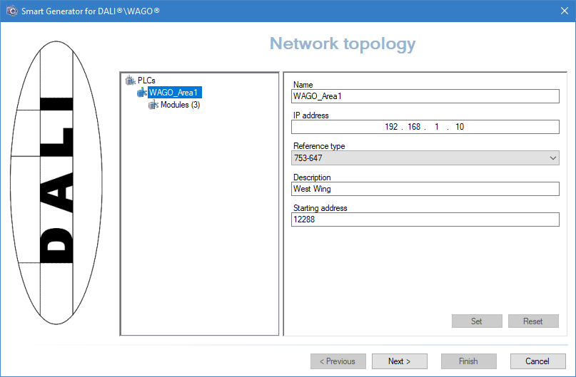
Right-click on the PLC's item in the left pane, then select Add PLC. The first PLC is added and its configuration is displayed in the right pane.
 Show picture
 -
Enter a name for the PLC or accept the suggested one. The PLC name is used as the device name in the communication configuration. It is also used as the first branch segment of all related variables and in the variable's Description property. For example, PLC1 Module 1 Ballast 1 lamp failure.
-
Enter the IP address of the PLC and select a reference type.
-
Enter a description for the PLC. The description appears in the tab corresponding to that PLC in the overview mimic (SGWDALI_PLCs).
-
Enter the starting address for the area in the PLC's memory in which the information for PcVue is to be found. The default address is 12288.
-
Click on the Set button to confirm your changes.
-
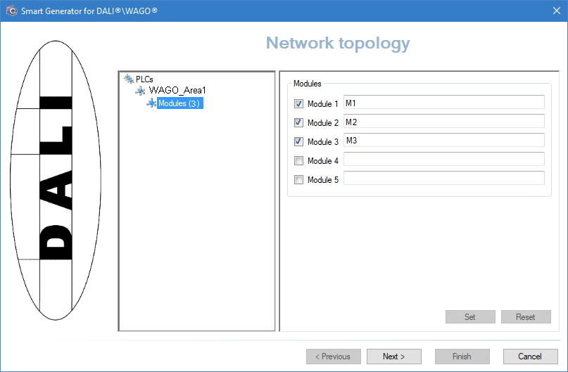
Click Modules under the PLC created. The number of modules already configured is shown in parenthesis.
Show picture -
Tick each module that is to be generated and enter a description for it. The description appears in the tab corresponding to that module in the overview mimic (SGWDALI_PLCs), and also in the Description property of some variables.
-
Click on the Set button to confirm your changes.
-
Repeat steps 2 to 10 for each DALI PLC in your system.
Configuring the mimics
After you have configured the PLCs and modules of the DALI\WAGO project, you can then configure the PcVue system mimics and the symbols they contain.
The following diagram illustrates the hierarchy of mimics that will be generated. For the PLC mimics, 'n' stands for the PLC number. For example SGWDALI_PLC_PLC1, SGWDALI_FTP_PLC2 etc. Navigation links between the mimics are automatically generated with SGWDALI_PLCs as the top-level mimic. The branch with which each mimic is opened is shown in parenthesis.
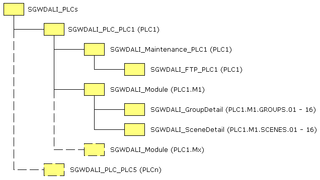
The mimics representing the PLCs (SGWDALI_PLC_PLCn) appear as tabs in the top-level mimic. The mimics representing the modules (SGWDALI_Module) appear as tabs in the PLC mimics.
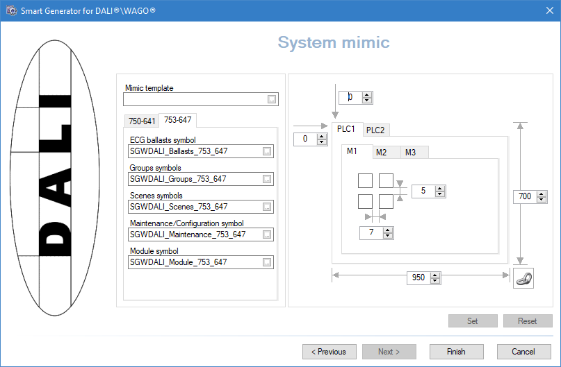
Click Next, the System mimic dialog opens. The information provided in this dialog is used to generate PcVue mimics and instantiate the symbols they will contain. ![]() Show picture
Show picture
-
To adjust the size and location of the PLC mimics and the spacing between the symbols within the Module tabs, enter a value in the number boxes around the tabs then click the Set button to confirm your changes.
You can use the Link icon button to retain the mimic's proportions when you set either the height or the width.
-
To apply a standard look and feel to the mimics generated, click on the ellipses in the Mimic template field and select a mimic template.
-
To select symbols containing graphical elements and animations from your PcVue project, click on the ellipses in the symbol fields. The default symbols are predefined within the smart generator. The symbols are copied to the library and instances of them are automatically generated in the mimics according to the number of PLCs and modules.
Due to the elaborated variable branching and substitution techniques used in the symbols, we recommend you modify the existing ones instead of creating new symbols from scratch. You can use the following technique:
-
Generate your DALI \WAGO project using the default symbols.
-
Copy the symbols that you want to change, edit them to give them the desired look and feel, then save them with an alternative name.
-
Start the smart generator again and from the right pane, select the previous import and click Synchronize from the left pane. The Smart Generator for DALI\WAGO dialog opens.
-
Go to the System mimic dialog and select the new symbols that you have created then click Finish to re-generate the project using the new symbols.
If you modify a default symbol of the smart generator and save it with the original name, it will be overwritten when you next run the smart generator.
The following table lists the symbols and the mimics that contain them:
| Symbol name | Used in |
| SGWDALI_Ballasts | SGWDALI_Module (mimic) |
| SGWDALI_BallastAssignment | SGWDALI_BallastDetail (mimic) |
| SGWDALI_Groups | SGWDALI_Module (mimic) |
| SGWDALI_GroupAssignment | SGWDALI_GroupDetail (mimic) |
| SGWDALI_Maintenance | SGWDALI_Maintenance_PLCn (mimic) |
| SGWDALI_Module | SGWDALI_Maintenance_PLCn (mimic) |
| SGWDALI_Scenes | SGWDALI_Module (mimic) |
| SGWDALI_Ballast | SGWDALI_Ballasts (symbol) |
| SGWDALI_Group | SGWDALI_Groups (symbol) |
| SGWDALI_Scene | SGWDALI_Scenes (symbol) |
Some symbols are contained within other symbols. In that case the name of the container symbol is given.
Click Finish. A progress dialog shows the generation of the various configuration elements. Your project is ready.
Synchronizing an existing import
When you synchronize an import, the smart generator compares the configuration elements available in the import file with those that have been imported previously to PcVue.
The synchronizing process takes into account any filter that you may have used previously with the import. For example if there are 400 variables in the import file and the previous use of the import was with a filter and created 100 variables in PcVue, synchronization will inform you that there are 300 new variables available for import.
-
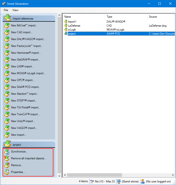
Select the import to synchronize in the right pane of the Smart Generators dialog. A list with actions appears under the Import references pane.
Show picture -
Click Synchronize. This will open the smart generator dialog in which you can reconfigure the import. If variables have been added to the import file since the last import, the smart generator will display the Import new variables dialog, inviting you to make either a full or a custom import of the remaining variables.
-
If you select full import, all variables not already in PcVue are imported.
-
If you select custom import, you can filter the variables using the Select variables dialog.
-
If the smart generator finds variables in PcVue that no longer exist in the import file, a list of the variables is displayed. Using this list, you can choose to remove some or all of the variables from PcVue.
You can choose to only remove imported configuration elements of a smart generator without removing the smart generator import itself. This can be done by right-clicking the import generated and selecting Remove all imported objects.
Generated configuration elements references
The DALI WAGO Smart Generator generates several configuration elements. They are listed here for references.
I/O variables
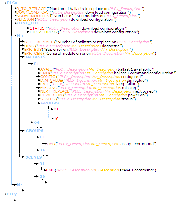
The variables that are generated depend on the number of PLCs and modules that are entered in the Network topology dialog. The variables are automatically mapped to the corresponding communication frames. The variable database has the following structure:
-
The blue elements represent a variable branch. For example: PLC1.M1.BALLASTS.01.
-
The red elements represent a bit variable. For example: PLC1.CONF_FILE.STATUS.
-
The yellow elements represent a register variable. For example: PLC1.CONF_FILE.RPM.
-
The green elements represent a text variable. For example: PLC1.M1.BALLASTS.01.DIM_VALUE.
-
PLCx and PLCy represent a PLC ID with x or y standing for a number.
-
Mn and Mz represent a module ID with n or z standing for a number.
Data acquisition configuration elements
The data acquisition configuration that is generated depends on the number of PLC's and modules configured in the Network topology dialog. The I/O variables are automatically mapped on the corresponding frames.
-
One network. The name is always IPDALI.
-
One device for each PLC. The name of the device is that provided in the Network Topology dialog.
-
The following frames. Frames starting with Mn are generated for each Module of each PLC, n is the Module number.
| Frames | Type | Access | Address range | Description |
| CFGMAINT | Word | Read/Write | DALI Cfg 12364..DALI Cfg 12367 | One for each PLC |
| Mn_BGROUPS | Word | Read | B Group 12482..B Group 12545 | Ballast groups |
| Mn_LDIAG | Word | Read | B Value 12388..B Value 12388 | DALI diagnostic |
| Mn_BINFOS | Word | Read | B Info 12390..B Info 12396 | Ballast information |
| Mn_BVALUES | Word | Read | B Value 12418..B Value 12418 | DALI values |
| Mn_BTYPES | Word | Read | B Type 12546..B Type 12546 | Ballast types |
| Mn_BCMDS | Word | Write | Cmd Mn B 12288..Cmd Mn B 12288 | Ballast commands |
| Mn_GCMDS | Word | Write | Cmd Mn G 12288..Cmd Mn G 12288 | Group commands |
| Mn_SCMDS | Word | Write | Cmd Mn S 12288..Cmd Mn S 12288 | Scene commands |
All frames with read access are configured with a scan rate of 1 second. The information here assume that the project is using the default start address 12288.
Main mimic
The main (top level) mimic is named SGWDALI_PLCs. It contains one tab for each PLC that is configured. Each PLC tab contains one tab called Configuration plus one tab for each Module that is configured. The names of the tabs are the same as the PLC and Module names entered in the Network topology dialog.
All the other mimics are used either in the main mimic's tabs or in pop-up mimics. They are designed to be used with a branch and are ineffective if opened without it. ![]() Show picture
Show picture
You can open the main mimic automatically when PcVue starts using the options in your project Settings dialog opened from Configure in the main menu then Project Settings.
PLCs and Modules maintenance mimics
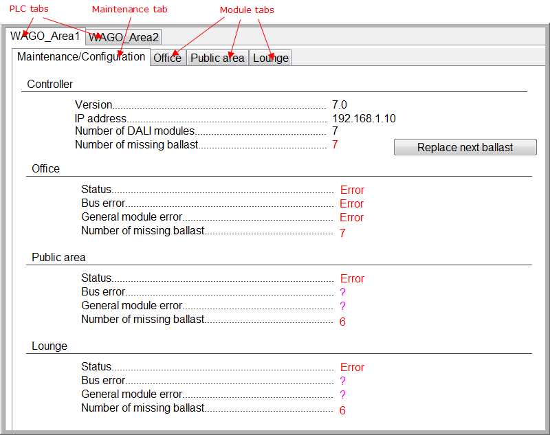
The Maintenance mimic is called SGWDALI_Maintenance_PLCname where PLCname is the name of a PLC. The PLC name is displayed as a tab of the PLC mimic, SGWDALI_PLC_PLCname. The Maintenance mimic contains two types of symbol.
-
SGWDALI_Maintenance - One instance.
-
SGWDALI_Module - One instance per configured module.
The following is a summary of each symbol, the variables it uses and any controls it provides.
A description of the full functionality is outside of the scope of this documentation. If you want to replace any symbol with one of your own, you must first carefully examine it using the PcVue graphic tools in order to fully understand the functionality it provides.
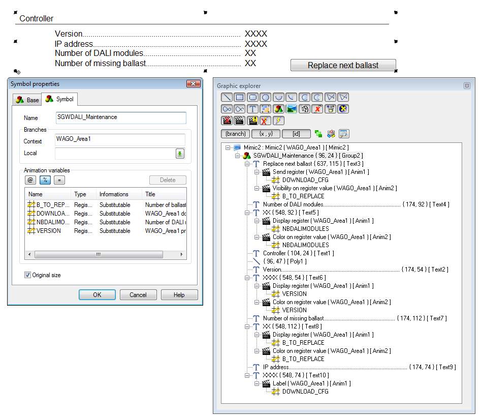
SGWDALI_Maintenance symbol:
Variables
-
PLCx.VERSION - The PLC version.
-
PLCx.NBDALIMODULES - The number of configured DALI modules for that PLC.
-
PLCx.B_TO_REPLACE - The number of missing modules for that PLC.
Controls
-
PLCx.DOWNLOAD_CFG and PLCx.B_TO_REPLACE - Control button to display and download the configuration. Only displayed if there are one or more ballasts to be replaced. Clicking on the button sends a value of 1 to the variable PLCx.DOWNLOAD_CFG.
Show picture
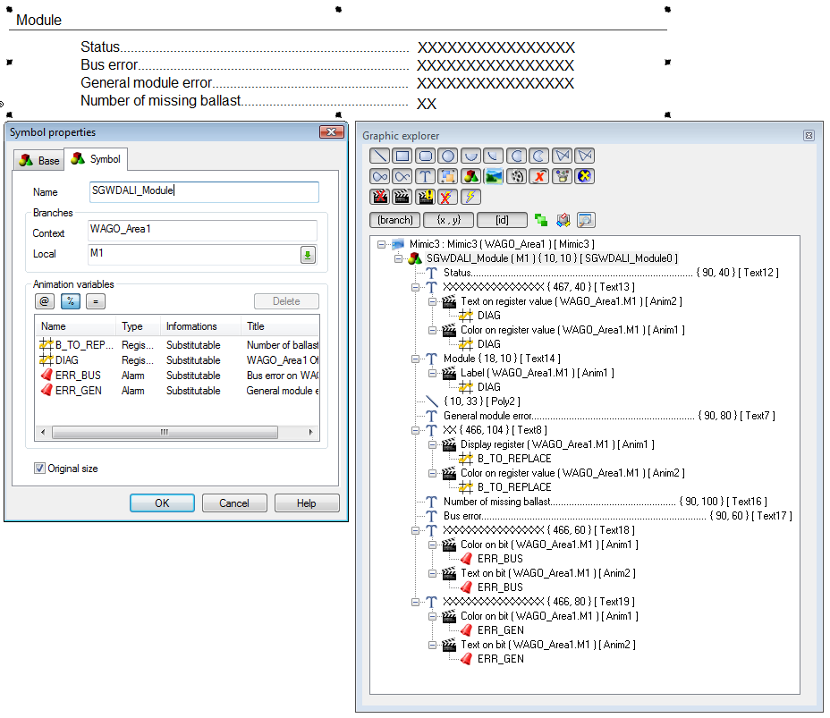
SGWDALI_Module symbol (one per module):
Variables
-
PLCx.My.STATUS - Module status.
-
PLCx.My.ERR_BUS - Module bus error.
-
PLCx.My.ERR_GEN - Module general error.
-
PLCx.My.B_TO_REPLACE - Number of missing ballasts.
Show picture
Modules mimics
The Modules mimic is named SGWDALI_Module. It is displayed as a tab of the PLC mimic, SGWDALI_PLC_plcname. ![]() Show picture
Show picture
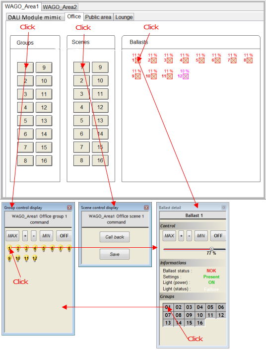
The mimic uses three symbols:
-
SGWDALI_Group - 16 instances, one for each possible group. They are located within the symbol SGWDALI_Groups which is used as a convenient container.
-
SGWDALI_Scenes - 16 instances, one for each possible scene. They are located within the symbol SGWDALI_Scenes which is used as a convenient container.
-
SGWDALI_Ballast - 64 instances, one for each possible ballast. They are located within the symbol SGWDALI_Ballasts which is used as a convenient container.
The following is a summary of each symbol, the variables it uses and any controls it provides.
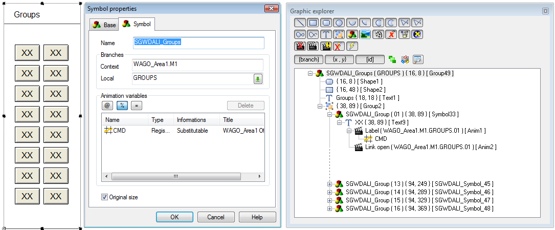
SGWDALI_Groups and SGWDALI_Group
Controls
-
PLCx.Mn.GROUPS.01.CMD - Control button to open the Group Control mimic, SGWDALI_GroupDetail. The variable provides the button label.
Show picture
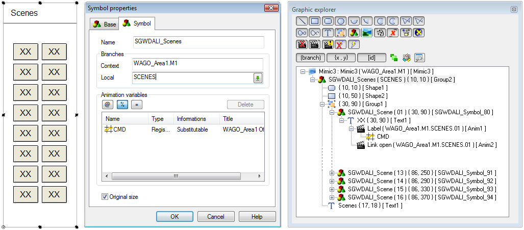
SGWDALI_Scenes and SGWDALI_Scene
Controls
-
PLCx.Mn.SCENES.01.CMD - Control button to open the Scene Control mimic, SGWDALI_SceneDetail. The variable provides the button label.
Show picture
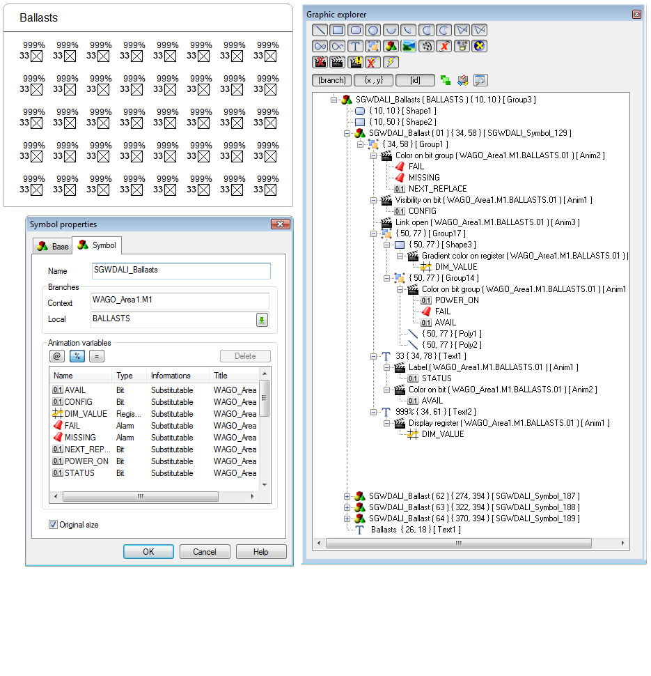
SGWDALI_Ballasts and SGWDALI_Ballast
Variables
-
PLCx.My.BALLASTS.nn.CONFIG - Not configured - OFF, Configured - ON (Symbol invisible if not configured)
-
PLCx.My.BALLASTS.nn.AVAIL - Available / (blinking), Not available
-
PLCx.My.BALLASTS.nn.FAIL - Failure - OFF, Failure - ON
-
PLCx.My.BALLASTS.nn.MISSING - Missing - OFF, Missing - ON
-
PLCx.My.BALLASTS.nnPOWERON - Power on - ON (blinking), Power on - OFF
-
PLCx.My.BALLASTS.nn.NEXT_REPLACE - Next to replace - OFF (blinking), Next to replace - ON
-
PLCx.My.BALLASTS.nn.DIM_VALUE - Dim value
-
PLCx.My.BALLASTS.nn.STATUS - Provides the ballast's ID (Extended attribute)
Controls
-
Control button to open the Ballast Detail mimic, SGWDALI_BallastDetail.
Show picture
Group control mimic
The Group control mimic is named SGWDALI_GroupDetail. ![]() Show picture
Show picture
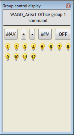
The Group control mimic can be opened either from one of the Group buttons in the Modules mimic (SGWDALI_Module) or from the one of the Group buttons in the Ballast Details mimic (SGWDALI_BallastDetail).
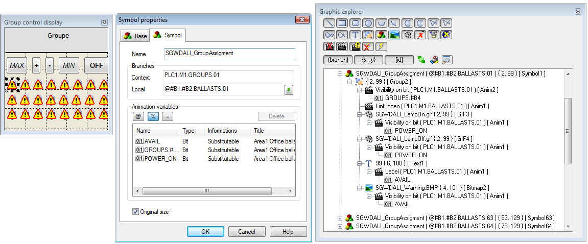
The Group Control mimic uses the SGWDALI_GroupAssigment symbol to display the status of each ballast.
SGWDALI_GroupAssigment
Variables
-
PLCx.My.BALLASTS.nn.#B4 - Does not belong - OFF, Does belong - ON (Invisible if does not belong)
-
PLCx.My.BALLASTS.nn.AVAIL.#T5 - Identity (number) of the ballast
-
PLCx.My.BALLASTS.nn.AVAIL - Not available - OFF, Available - ON
-
PLCx.My.BALLASTS.nn.POWER_ON - Power on - ON , Power on - OFF
Controls
-
Control button to open the Ballast Details mimic, SGWDALI_BallastDetail.
Show picture
You can use the mimic ballast controls to set:
-
MAX - Sends a value of 305 to the PLC (Variable PLCx.My.GROUPS.nn.CMD)
-
MIN - Sends a value of 306 to the PLC (Variable PLCx.My.GROUPS.nn.CMD)
-
Up (+) - Sends a value of 301 to the PLC (Variable PLCx.My.GROUPS.nn.CMD)
-
Down (-)- Sends a value of 302 to the PLC (Variable PLCx.My.GROUPS.nn.CMD)
-
OFF - Sends a value of 300 to the PLC (Variable PLCx.My.GROUPS.nn.CMD)
Scene control mimic
The Scene Control mimic is named SGWDALI_SceneDetail. ![]() Show picture
Show picture
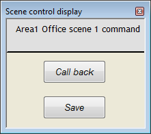
The Scene control mimic is opened from one of the Scene buttons in the Modules mimic (SGWDALI_Module) and it contains:
-
Call back - Sends a value of 1000 to the PLC (Variable PLCx.My.SCENES.nn.CMD).
-
Save - Sends a value of 1001 to the PLC (Variable PLCx.My.SCENES.nn.CMD).
Ballast details mimic
The Ballast Details mimic is named SGWDALI_BallastDetail. ![]() Show picture
Show picture
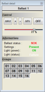
The Ballast Details mimic can be opened either from one of the Ballast buttons in the Modules mimic (SGWDALI_Module) or from the one of the Ballast buttons in the Group control mimic (SGWDALI_GroupDetail).
Controls
You can use the mimic controls to set:
-
MAX - Sends a value of 305 to the PLC (Variable PLCx.My.GROUPS.nn.CMD)
-
MIN - Sends a value of 306 to the PLC (Variable PLCx.My.GROUPS.nn.CMD)
-
Up (+) - Sends a value of 301 to the PLC (Variable PLCx.My.GROUPS.nn.CMD)
-
Down (-) - Sends a value of 302 to the PLC (Variable PLCx.My.GROUPS.nn.CMD)
-
OFF - Sends a value of 300 to the PLC (Variable PLCx.My.GROUPS.nn.CMD)
Mimic animations:
-
Ballast status (Variables PLCx.My.BALLASTS.nn.STATUS, PLCx.My.BALLASTS.nn.DIM_VALUE)
-
Dim Value >100, Status = 0: OK
-
Dim Value >100, Status = 1/0: BAD
-
-
Settings (Variable PLCx.My.BALLASTS.nn.AVAILABLE)
-
Dim Value >100, Available= 0: Missing
-
Dim Value <>100, Available= 1 : Available
-
-
Light power (Variable PLCx.My.BALLASTS.nn.POWER_ON)
-
Light status: (Variable PLCx.My.BALLASTS.nn.FAIL)
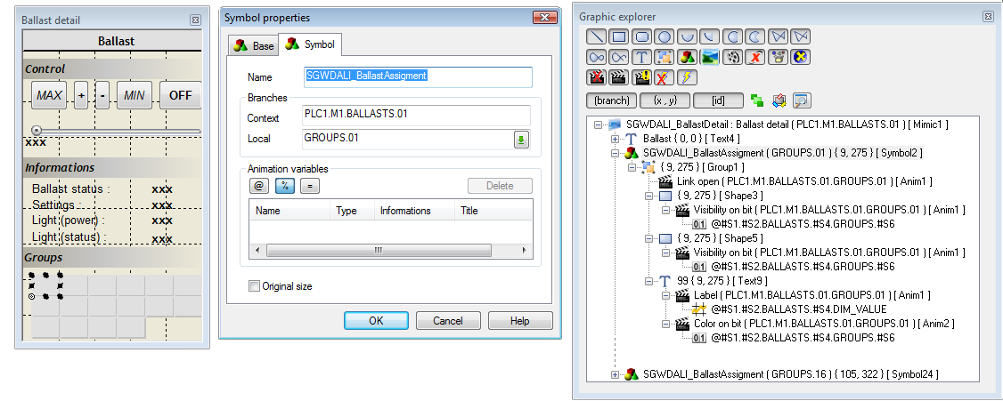
SGWDALI_BallastAssigment:
Variables
-
PLCx.My.BALLASTS.nn.GROUPS.yy - Ballast is part of the Group - ON , Ballast is not part of the group - OFF.
Controls
-
Control button to open the Group Control mimic, SGWDALI_GroupDetail.
Show Picture