How to import a Yokogawa Stardom configuration
The Smart Generator for Stardom generates the following in the PcVue project based on a Yokogawa Stardom configuration:
-
OPC data acquisition between PcVue and the Stardom FCN-FCJ OPC Server.
-
I/O variables including mapping onto the OPC-DA client driver.
-
Mimics by associating HMI symbols with the Stardom project's Program Organization Units (POUs). The mimics that can be generated are: Trend mimics, control group mimics, graphics mimics (free mimics), and the system overview mimic. The latter mimic includes: One controller symbol for each controller and an information panel (Faceplate) for each controller type (FCN and FCJ).
The smart generator uses the Stardom Library to provide the specialized components for the HMI:
-
The Toolbox mimic.
-
Mimic templates.
-
Function key settings.
-
NPAS/POU symbols.
-
Global variable symbols.
-
Other symbols.
See the Stardom Library folder section of this topic for more information.
Prerequisites
-
You have exported the Stardom project. This is a file exported from the Yokogawa Stardom Logic Designer in IEC61131-3 (ASCII) format.
-
You have installed and stored the Stardom library folder in the PcVue project sub-folder LIB.
To operate PcVue in communication with the Stardom network, the Stardom FCN-FCJ OPC Server must be running.
The Stardom Logic Designer does not need to be running during the import process.
Refer to the overview topic Smart Generators overview to learn more.
Selecting the source data
Before you start the import process, we recommend that you back up the PcVue variables configuration in case of any problems occurring during the import process. The variable configuration is stored in the file VAREXP.DAT in the project's C folder.
Make sure that PcVue is shut down before copying the file.
-
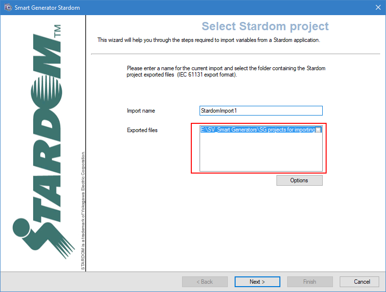
Go to Configure then Smart Generators and click New Stardom import. The Smart Generator Stardom dialog opens with the Import name field specified. You can change this name.
 Show picture
 -
Click on ellipses button in Exported files field and select the location of the Stardom project files to import. The exported files should be in the IEC 61131 format.
-
Click the Advanced/Options button, then select a server list and a client list in the Networking list tab to define the behavior of PcVue variables for a multi-station project.
The lists of servers and clients must already have been created in PcVue and the station from which you run the smart generator must be in the servers list.
-
Select the OPC server tab and select from the drop downs the default OPC server and group. This configuration applies to global variables only.
The resources declared in the OPC server configuration file (FCXCNF.CSV) must be the same as those declared in the Stardom project.
-
Select the Options tab and select from the drop-down the encoding for the exported files then click OK to validate.
Selecting POUs and import type
After you have selected the source data and configured the networking lists and options of the import via the Select project dialog, the next step is to select the POUs (Program Organization Unit) you want to import and the import type.
-
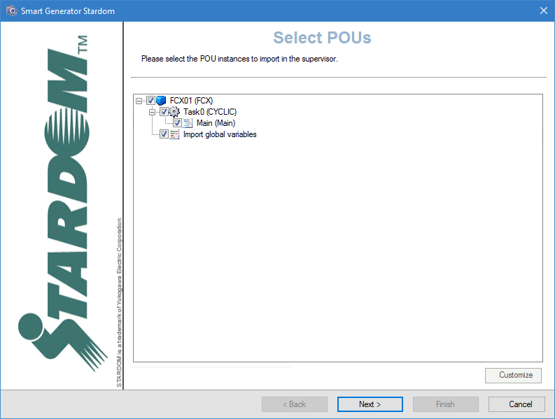
Click Next, the Select POUs dialog opens. Here the POUs are displayed in a tree structure of three levels. The first level is the Controller, the second one is the Task and the third is the Program. Select the items to be imported.
Show picture -
To customize POUs, select them and click Customize. This opens the POUs dialog which enables you to configure several properties for all instances of POUs selected. The list view pane on the left displays the instance name of the selected items. For example: FCX01/Task0/PRG1/PAS_PID_1. The right side of the list view displays the variables. For example: PAS_PID.
In the list view, you can sort the list by clicking on the column headers.
You can also use the Windows keyboard shortcuts for making multiple selections. (Shift+Click and Ctrl+Click).
The grid pane of the right of the dialog displays the properties configured in the STARDOMIMPORTCONFIGURATION.XML file. Click Apply to apply the property changes to the selected POU instances.
-
Click Next, the Import type dialog opens. Select the import type you need. There are three options:
-
Import data - If selected, it only imports the configuration necessary to generate PcVue variables.
-
Import HMI- If selected, it only imports the configuration necessary to generate and structure PcVue mimics (HMI).
-
Full import - If selected, it imports the configuration and generate both the variables and mimics (HMI).
-
Selecting and customizing the variables
After you have selected the POUs to import and the import type via the Select import type dialog, the next step is to select the import type for the global variables, then to select and customize the variables you want to generate.
-
Click Next, the variable import process is initialized and the Select import type dialog opens. Select the type of import you need:
- Custom import if you want to access the Select variables dialog in which you can filter and manually select the list of variables to import.
- Full import if you want to generate variables for all source data.
-
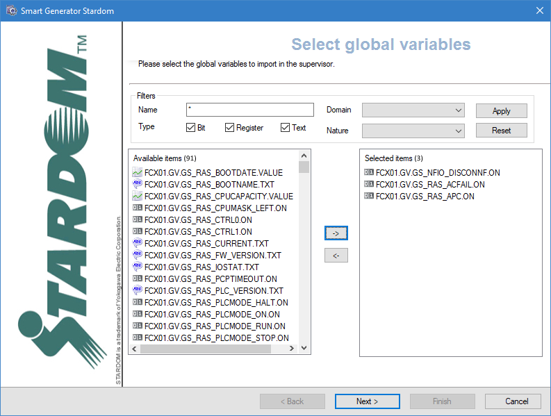
(Custom import option) Adjust the filters to find the variables to import. The Name field allows to filter the list of variables according to the name in the source data. You can use wildcards, the asterisk (matches any number of characters) and the question mark (matches a single character).
For example:
'Pump1' would only match a source data named 'Pump1'.
'Pump?' would match 'Pump1' or 'Pump2' etc. but not 'Pump10'.
'Pump*' would match 'Pump1', 'Pump2' and 'Pump10' but also 'Pumpkin'.The variables that match the filter appear in the Available Items pane.
-
(Custom import option) Select the variables filtered in the Available items pane for import and click the right-arrow -> button. The variables in the Selected items pane are to be imported and generated.
-
Click Next, the Customize global variables dialog opens. This dialog allows you to modify the properties of multiple variables at a time. Select the variables to modify in the left pane and adjust the properties that are not grayed out in the right pane. Each property that you modify will be applied to all selected variables.
Configuring the HMI
After selecting and customizing the variables to import via the Customize global variables dialog, the next step is to configure the HMI items to be imported.
After making any changes to the properties of an element, you must use click Apply button in the toolbar before selecting another element or clicking Finish. Failing to do so results in the loss of any changes made.
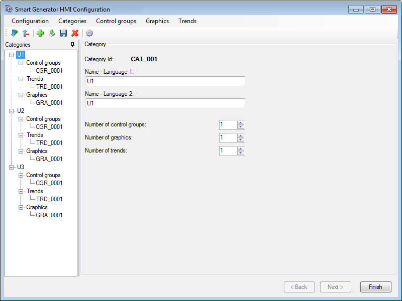
Click Next, the Smart Generator HMI Configuration dialog opens. Here you can configure the structure and some of the contents of the mimics that form the HMI. In addition to the menu and toolbar, the dialog contains two main areas:
-
The Categories configuration tree in the left pane. Right clicking on a node in the configuration tree displays a context menu. Categories are groups that contain the mimics generated by the Smart Generator. Categories are displayed and selected at run-time using the Toolbox mimic. One Category is automatically generated for each Unit. By default, each Category contains one Control Group (mimic), one Trend (mimic), and one Graphic (process mimic).
-
The properties for the item selected in the Categories tree in the right pane.
The following are all possible ways in which you can modify the structure and some of the contents of the mimics that form the HMI:
-
To add a new category, click in the category tree then the Add icon button in the menu. A new category, with default properties, is added to the end of the category tree. Category ID's are assigned automatically and cannot be edited. A maximum of 1000 categories can be created. The following properties can be edited:
Show picture-
Name - Language 1 - The identity of the category, if language 1 is selected, The name appears in the menu mimics at runtime. Up to 20 characters or ideograms.
-
Name - Language 2 - The identity of the category, if language 2 is selected, The name appears in the menu mimics at runtime. Up to 20 characters or ideograms.
-
Number of control groups - The number of control group mimics in the selected category. Range: 1..1000.
-
Number of graphics - The number of process mimics in the selected category. Range: 1..1000.
-
Number of trends - The number of trend mimics in the selected category. Range: 1..1000.
To delete a category, select it then click the Delete icon button in the toolbar. The category and all its mimics are deleted.
-
The order in which categories appear in the menu mimics at run-time is the same as configured in the categories tree. Be careful when adding or deleting categories as there are no specific tools to reorder them.
If you reduce the number of nodes below that were previously configured, a dialog warns you that related mimics will be deleted. Deleted mimics are moved to the project's sub folder \W\BAK.
-
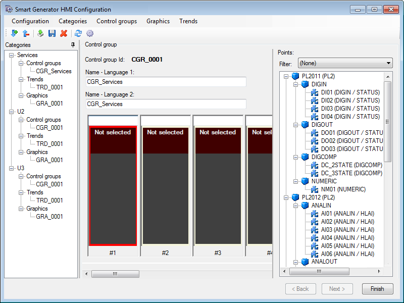
To add a new control group, select the node representing the category to which the control group is to be added then click Control groups in the main menu then Add control group. A new control group with default properties will be created with the following language properties:
Show picture-
Name - Language 1 - The name of the control group. If language 1 is selected, The name appears in the menu mimics at runtime. Up to 20 characters or ideograms.
-
Name - Language 2 - The name of the control group. If language 2 is selected, The name appears in the menu mimics at runtime. Up to 20 characters or ideograms.
-
-
To display the faceplate type and instance name, expand the tree structure of object PAS/POU in the right pane and select one of the eight faceplate (symbol) slots then double-click on the object's entry in the tree structure. Its faceplate type and instance name are shown in the slot's header and the next slot to the right is selected.
-
To add a new graphic, select the node representing the category to which the graphic is to be added then click Graphics in the main menu then Add graphics. A new graphic with default properties will be created with the following language properties:
-
Name Language 1 - The name of the graphic. If language 1 is selected, The name appears in the menu mimics at runtime. Up to 20 characters or ideograms.
-
Name Language 2 - The name of the graphic. If language 2 is selected, The name appears in the menu mimics at runtime. Up to 20 characters or ideograms.
To delete a graphic, select it then using the Delete icon button in the toolbar. The node is removed from the tree structure.
The HMI objects are designed for a display resolution of 1280x1024 pixels and for Full HDMI.
-
-
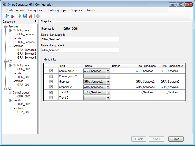
To configure mimic links, select a graphics from the Categories tree. The Graphics configuration is displayed in the right pane. You can configure links with up to six other mimics, two each of control groups, graphics and trends, within the category. For each link, you can configure the following properties:
Show picture-
Link - If selected, it enables the link configuration.
-
Name - If specified, it opens the names of the control group/graphic/trend.
-
Branch - If specified, it defines the branch (if any) for the link.
-
Title Language 1 - If specified, it defines the text that appears on the button at run-time if using language 1.
-
Title Language 2 - If specified, it defines the text that will appear on the button at run-time if using language 2.
By default, the two links for graphics are populated with the previous and next mimic in the category.
-
-
To add a new trend, select the node representing the category to which the trend is to be added then click Trends in the main menu then Add trends. A new trend with default properties will be created with the following language properties:
-
Name Language 1 - The name of the trend. If language 1 is selected, The name appears in the menu mimics at runtime. Up to 20 characters or ideograms.
-
Name Language 2 - The name of the trend. If language 2 is selected, The name appears in the menu mimics at runtime. Up to 20 characters or ideograms.
You must manually configure the Trend viewer after the Smart Generator has completed the generation. This is because each trend mimic created by the Smart Generator contains a single unconfigured Trend viewer.
-
Click Finish to complete the generation process.
Synchronizing an existing import
When you synchronize an import, the smart generator compares the configuration elements available in the import file with those that have been imported previously to PcVue.
The synchronizing process takes into account any filter that you may have used previously with the import. For example if there are 400 variables in the import file and the previous use of the import was with a filter and created 100 variables in PcVue, synchronization will inform you that there are 300 new variables available for import.
-
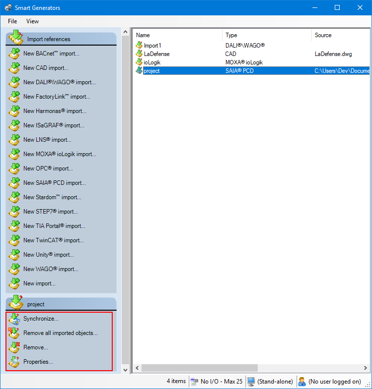
Select the import to synchronize in the right pane of the Smart Generators dialog. A list with actions appears under the Import references pane.
Show picture -
Click Synchronize. This will open the smart generator dialog in which you can reconfigure the import. If variables have been added to the import file since the last import, the smart generator will display the Import new variables dialog, inviting you to make either a full or a custom import of the remaining variables.
-
If you select full import, all variables not already in PcVue are imported.
-
If you select custom import, you can filter the variables using the Select variables dialog.
-
If the smart generator finds variables in PcVue that no longer exist in the import file, a list of the variables is displayed. Using this list, you can choose to remove some or all of the variables from PcVue.
You can choose to only remove imported configuration elements of a smart generator without removing the smart generator import itself. This can be done by right-clicking the import generated and selecting Remove all imported objects.
Stardom Library folder
The smart generator uses the Stardom Library to provide the specialized components for the HMI:
-
The Toolbox mimic.
-
Mimic templates.
-
Function key settings.
-
NPAS/POU symbols.
-
Global variable symbols.
-
Other symbols.
The Library folder for Stardom is stored in the PcVue library folder that by default is in the project sub-folder LIB. Here is a list of the files supplied in the library.
| Name | Subfolder | Description |
| Configuration files | ||
| STARDOMIMPORTCONFIGURATION.XML | TP | Includes Templates for all controllers, program instances and POUs as well as global definitions such as OPC groups. |
| STARDOMIMPORTCONFIGURATIONHMI.XML | TP | A list of configuration items that are to be created for each category (Control Group, Graphics and Trend). |
| Mimic templates | ||
| TPL_ALARMS | WT | For Alarm mimics. |
| TPL_CONTROLGROUP | WT | For Control Group mimics. |
| TPL_TRENDS | WT | For Trend mimics. |
| TPL_GRAPHICS | WT | For Graphics mimics. |
| TPL_MENU | WT | For Menu mimics. |
| TPL_SYSTEM | WT | For System mimics. |
| Template files | ||
| TOOLBOX.SIT | W | For Toolbox mimic. |
| TOOLBOX.SIT.BINARY | - | - |
| TRD_xxxx.SIT | W | For Trend mimics. |
| GRA_xxxx.SIT | W | For Graphics mimics. |
| CGR_xxxx.SIT | W | For Control Group mimics. |
| ALA_xxxx.SIT | W | For Alarm mimics. |
| SYS_xxxx.SIT | W | For System Overview mimics. |
| Mimics | ||
| MENU_CONTROLGROUPS | W | Including the Control Group menu. |
| MENU_GRAPHICS | W | Including the Graphics menu. |
| MENU_TRENDS | W | Including the Trends menu. |
| [POU Name]_Settings | W | Settings mimic. One for each supported POU. |
| Symbols | ||
| [POU Name] | S | POU symbol. One for each supported POU. |
| Images | ||
| [POU Name].png | B | Images of POU symbols to be used by the smart generator. |
| POU_GENERIC.png | B | Image to be used by the smart generator for POUs without an image of their symbol. |